Method for manufacturing turbine blade and turbine blade

A technology of turbine blades and gas turbines, which is applied in the direction of blade support elements, gas turbine devices, stators, etc., which can solve the problems of inability to cool turbine blade parts and achieve high-efficiency cooling

Inactive Publication Date: 2002-11-20
SIEMENS AG
View PDF2 Cites 2 Cited by
  • Summary
  • Abstract
  • Description
  • Claims
  • Application Information

AI Technical Summary

Problems solved by technology

This prevents targeted cooling of highly stressed turbine blade components

Method used


Image

  • Method for manufacturing turbine blade and turbine blade
  • Method for manufacturing turbine blade and turbine blade
  • Method for manufacturing turbine blade and turbine blade

Examples


Embodiment Construction

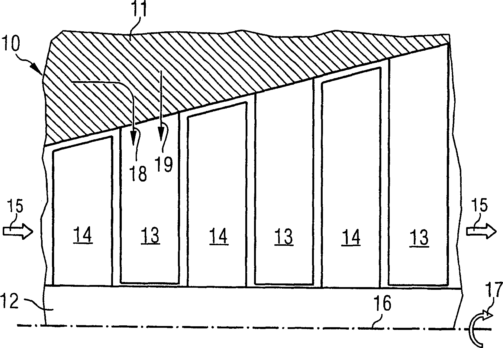
[0024] figure 1 A longitudinal section through a gas turbine 10 with a housing 11 and a rotor 12 is shown. A set of guide vanes 13 is provided on the housing 11 , and a set of rotor blades 14 is provided on the rotor 12 . Hot gas flows through the gas turbine 10 in the direction indicated by arrow 15 causing the rotor 12 to rotate about its axis of rotation 16 in the direction indicated by arrow 17 . Cooling medium is fed in in the direction of arrows 18, 19 for cooling. For the sake of simplicity, only the feed channel in one guide vane 13 is shown. Of course, the invention is not limited to a guide blade 13 , the invention is equally suitable for a rotor blade 14 .

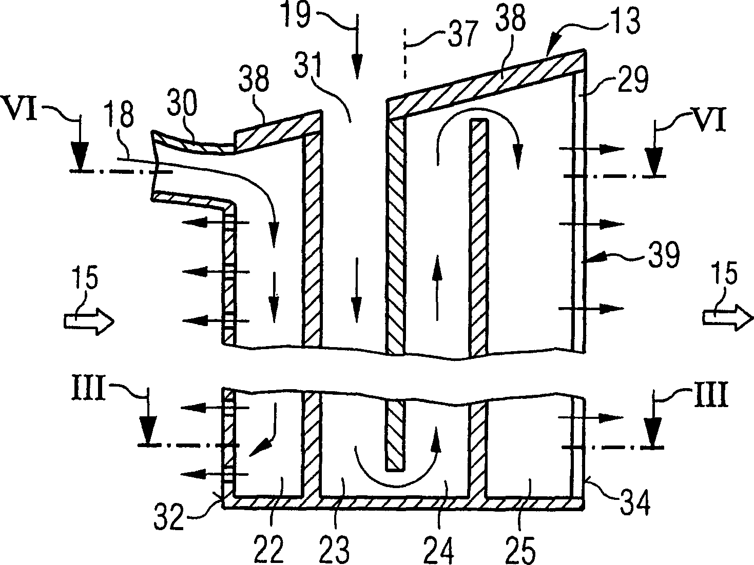
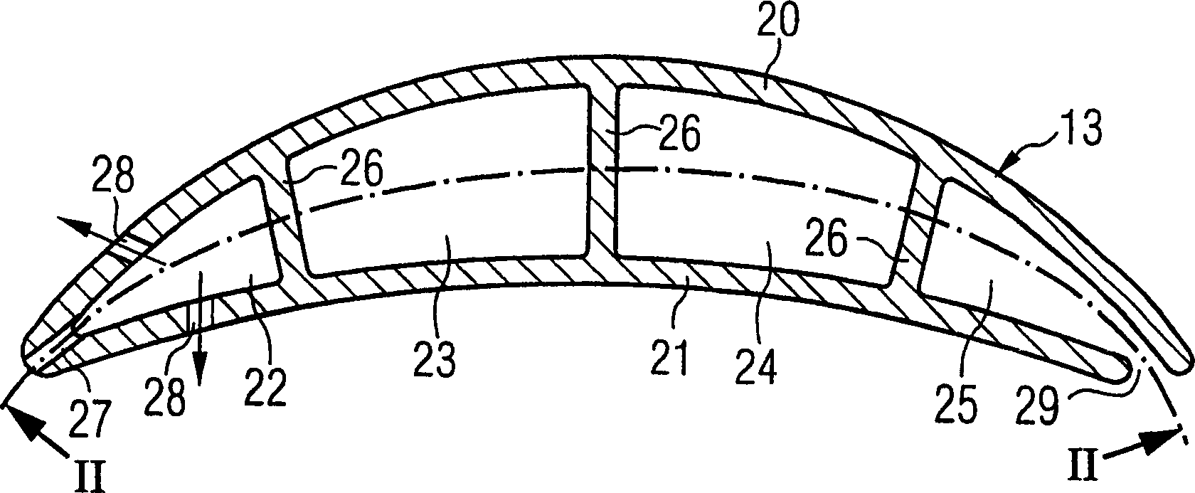
[0025] figure 2 A longitudinal section through a guide vane 13 is shown, image 3 Its cross section is shown. The guide vane 13 has a platform 38 for fastening to the casing 11 and an airfoil 39 around which the hot gas flows. The airfoil 39 is formed by a suction side wall 20 and a pressure side wall 21...


PUM


Abstract

The invention relates to a method for producing a turbine blade (13, 14) having at least one chamber (22; 23, 24, 25) and at least one inlet channel (30, 31) for feeding a cooling medium into the chamber ), the input channel (30) forms an included angle with the longitudinal axis (37) of the turbine blades (13, 14). According to the invention, a core (35) with a lug (33) is used to form the inlet channel (30), the core is separated from the mold (40), and after being removed from the mold, the inlet channel of the turbine blade (30) is initially closed and can be opened by post-processing. The invention also relates to a turbine blade, in particular a turbine blade for a gas turbine (10), manufactured by the method described above, wherein the inlet channel (30) forms an angle and is substantially parallel to the longitudinal axis (37) of the turbine blade In the flow direction (15) of the working medium through the turbine (10). Therefore, the cooling medium can be introduced along the axial direction of the turbine (10).

Description

technical field [0001] The invention relates to a method for producing a turbine blade having at least one chamber and at least one inlet channel for feeding a cooling medium into the chamber, wherein at least one inlet channel is at an angle to a longitudinal axis of the turbine blade . The invention also relates to a turbine blade, in particular for a gas turbine, having at least one chamber and at least one feed channel for a cooling medium into the chamber. Background technique [0002] Such a method and turbine blade are disclosed in US 5,599,166. The turbine blade has two meandering chambers that are separated from each other and each communicate with an inlet channel for a cooling medium. The two input passages are substantially parallel to the longitudinal axis of the turbine blade. [0003] US 5,413,458 describes another turbine blade which also has at least one chamber for filling with a cooling medium. In this case, the cooling medium is s...

Claims


Application Information

Patent Timeline
IPC IPC(8): F01D5/18F01D9/02F01D25/12F02C7/00
CPCF01D5/187F01D25/12F05D2230/10F05D2230/21Y10T29/49336Y10T29/49339
Inventor 彼得·蒂曼
Owner SIEMENS AG
Why Eureka
Try Eureka