
Stuffing-throwing fluidized bed membrane bioreactor and water treating method

A bioreactor, fluidized bed technology, applied in the field of water and wastewater treatment, can solve the problem of low microbial degradation efficiency, and achieve the effects of reducing the amount of suspended sludge, resisting shock loads, and having a compact structure

Inactive Publication Date: 2002-10-16
TSINGHUA UNIV
View PDF1 Cites 34 Cited by
  • Summary
  • Abstract
  • Description
  • Claims
  • Application Information

AI Technical Summary

Problems solved by technology

Domestic and foreign patent documents using membrane-bioreactors for microbial suspension growth to treat sewage, such as "suction built-in membrane-bioreactor (Patent No. 97228698.5)", this patent uses suction built-in membrane-bioreactor to treat Domestic sewage is reused, but when the concentration of organic pollutants is low, the degradation efficiency of microorganisms in the suspended growth membrane-bioreactor is low

Method used


Image

  • Stuffing-throwing fluidized bed membrane bioreactor and water treating method
  • Stuffing-throwing fluidized bed membrane bioreactor and water treating method
  • Stuffing-throwing fluidized bed membrane bioreactor and water treating method

Examples


Embodiment 1

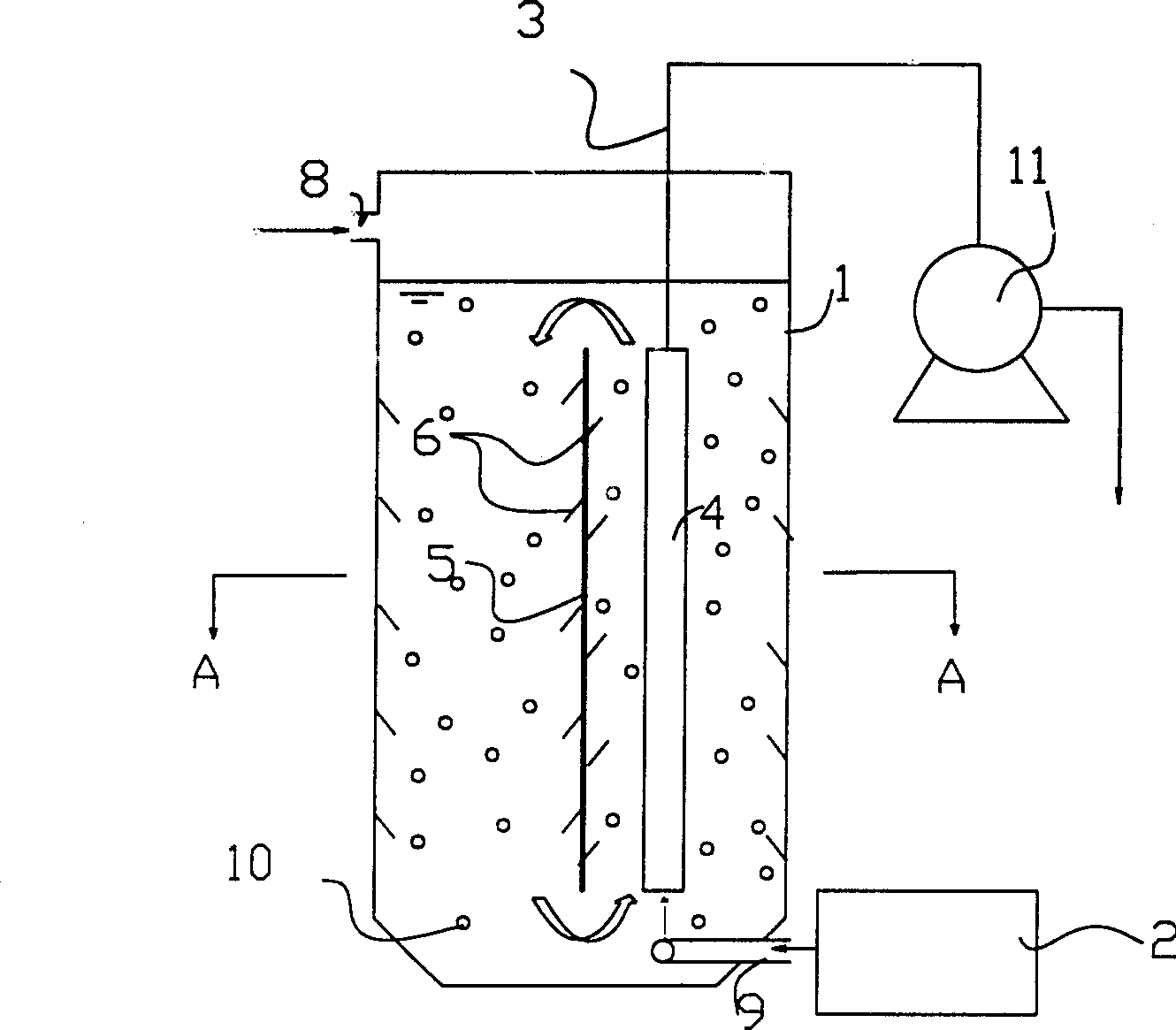
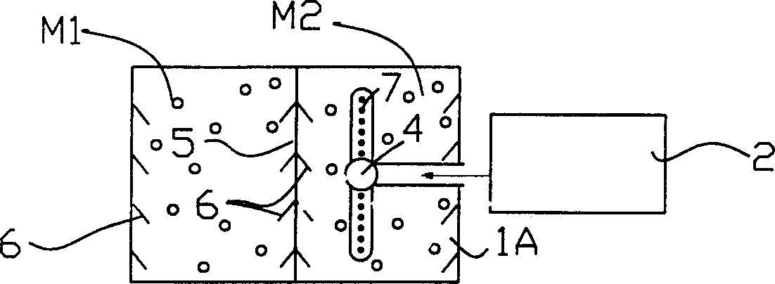
[0025] figure 1 Represent the fluidized bed type membrane-bioreactor device of embodiment one, this device is by cuboid reactor shell 1, air supply device 2, adopts perforated pipe air distribution device 7, outlet pipe 3, membrane module 4, deflector 5. The cyclone device 6 is composed, and a suction pump 11 is arranged on the outlet pipe of the reactor. The reactor shell 1 is a hollow cuboid structure, its axis is perpendicular to the horizontal plane, and its upper side is provided with a water inlet pipe 8,

[0026] The gas inlet 9 of the air supply device 2 is directly below the membrane module. The membrane module can be a curtain-shaped hollow fiber membrane module, a bundle-shaped hollow fiber membrane module, a flat-plate membrane module or a tubular membrane module. The deflector 6 arranged in the middle of the device divides the interior of the device into left and right regions, which are respectively the upflow region M2 and the downflow region M1. The water ou...

Embodiment 2

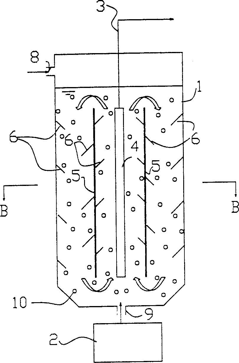
[0029] image 3It is the fluidized bed type membrane-bioreactor device of embodiment 2 with filler added. The device consists of a cylindrical reactor shell 1, an air supply device 2, a perforated pipe air distribution device 7, a water outlet pipe 3, a membrane module 4, a guide tube 5 and a swirl plate 6. In the figure, the upper side of the reactor is provided with a water inlet pipe 8, and the center of the bottom is provided with a gas inlet 9 from an air supply device, and the 9 is directly below the membrane module. The membrane modules can be bundled hollow fiber membrane modules or tubular membrane modules. The guide cylinder provided in the middle of the device divides the interior of the device into two areas, the central area Q1 and the peripheral area Q2. The water outlet pipe 3 is connected with the collection port of the membrane module 4, and the collection port of the membrane module can be arranged at the upper part or the lower part of the membrane module....


PUM


Abstract

The present invention relates to water, including waste water, treating technology. Stuffing with certain specific surface area is thrown into reactor and under sufficient aeration condition and the action of gas density difference, inflecting board and cyclone, the triphase of solid, liquid and gas inside the reactor reaches fluidized state and forms cyclonic circulation. the adsorption and growth of microbes on the stuffing results in even high organic matter eliminating efficiency and the stuffing has certain adsorption to soluble organic matter in water. The suspended microbes in the bioreactor and those in the surface of membrane are reduced. The present invention is especially suitable for use in relatively lower organic matter density. Compared with traditional membrane bioreactor,the present invention can avoid the pollution to membrane and make system operate more stably and at lower power consumption.

Description

technical field [0001] The invention relates to a membrane-bioreactor and a water treatment method, belonging to the technical field of water and waste water treatment. Background technique [0002] Membrane-bioreactor is a water and wastewater treatment method that organically combines biological reaction unit and membrane separation technology. Microbes can be retained through membrane separation, and the separation of hydraulic retention time and sludge age can be realized. The pollutant treatment efficiency is high, the effluent quality is good and stable, and the residual sludge output is small; and the membrane-bioreactor device is compact in structure and easy to realize automatic control. . The suspended growth membrane-bioreactor (without filler addition) has been applied in the fields of sewage treatment and reuse, such as the treatment and reuse of urban domestic sewage, the treatment of high-concentration organic wastewater, and the treatment of fecal wastewater...

Claims


Application Information

Patent Timeline
IPC IPC(8): C02F1/44C02F3/00C02F3/08C02F3/10
CPCY02W10/10
Inventor 黄霞莫罹文湘华
Owner TSINGHUA UNIV
Learn More