
Sampling time-clock generation circuit, data transmission control device and electronic equipment

A technology of sampling clock and generating circuit, which is applied in the direction of electric digital data processing, electric pulse generator circuit, synchronization device, etc., can solve the problems of long design period, hindering the macro-unitization of data transmission control device, high device cost, etc., and achieve reliable Improvement of performance, improvement of cost reduction, seeking the effect of treatment

Inactive Publication Date: 2002-05-22
SEIKO EPSON CORP
View PDF0 Cites 14 Cited by
  • Summary
  • Abstract
  • Description
  • Claims
  • Application Information

AI Technical Summary

Problems solved by technology

[0009] However, such a method of manually arranging circuits and wiring has problems of long design period and high device cost compared with an efficient circuit design method using HDL (Hardware Description Language) circuit synthesis and automatic layout and wiring. At the same time, it also hinders the macro-unitization of data transfer control devices (physical layer circuits, logical layer circuits)

Method used


Image

  • Sampling time-clock generation circuit, data transmission control device and electronic equipment
  • Sampling time-clock generation circuit, data transmission control device and electronic equipment
  • Sampling time-clock generation circuit, data transmission control device and electronic equipment

Examples


Embodiment Construction

[0067] Hereinafter, this embodiment will be described in detail using the drawings.

[0068] In addition, the present embodiment described below does not limit the content of the present invention described in the scope of the claims in any way. In addition, all the structures demonstrated in this Example are not limited to the essential conditions of the structure of this invention.

[0069] 1. Composition and work

[0070] 1.1 Data transmission control device

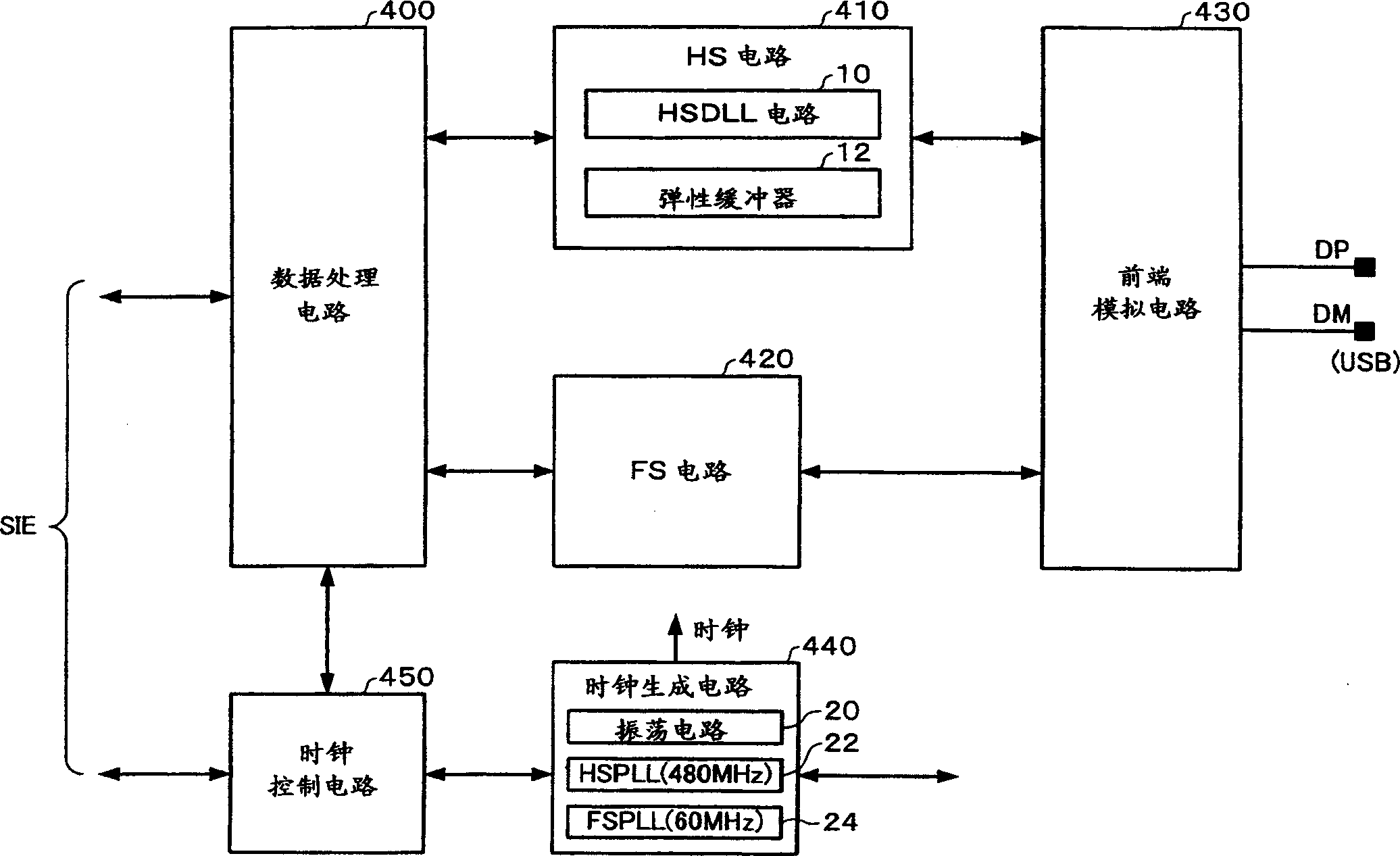
[0071] figure 1 is a diagram showing a configuration example of the data transfer control device of this embodiment.

[0072] The data transfer control device of this embodiment includes a data processing circuit 400 , a HS (high speed) circuit 410 , a FS (full speed) circuit 420 , a front-end analog circuit 430 , a clock generation circuit 440 and a clock control circuit 450 . Furthermore, the structure of the data transfer control device of the present invention does not necessarily include figure 1 All of the ...


PUM


Abstract

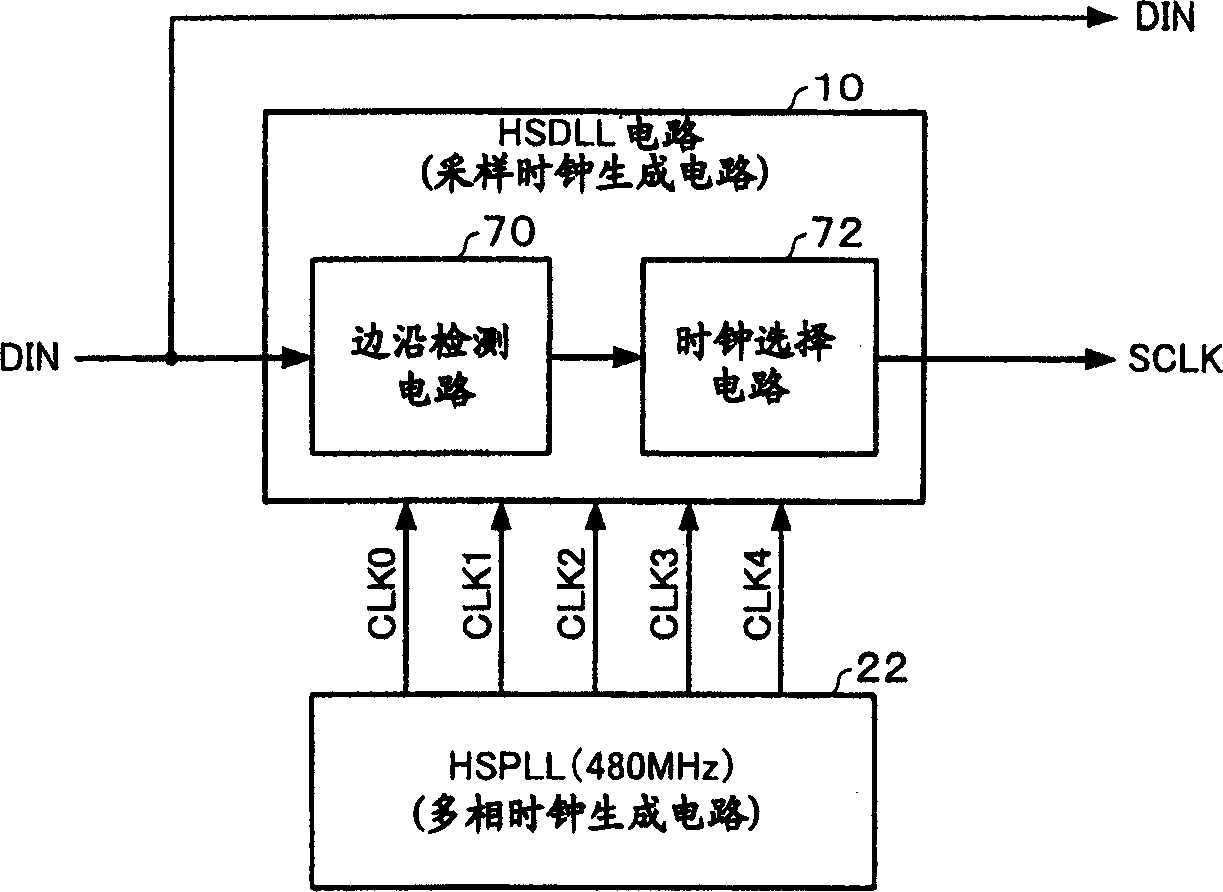
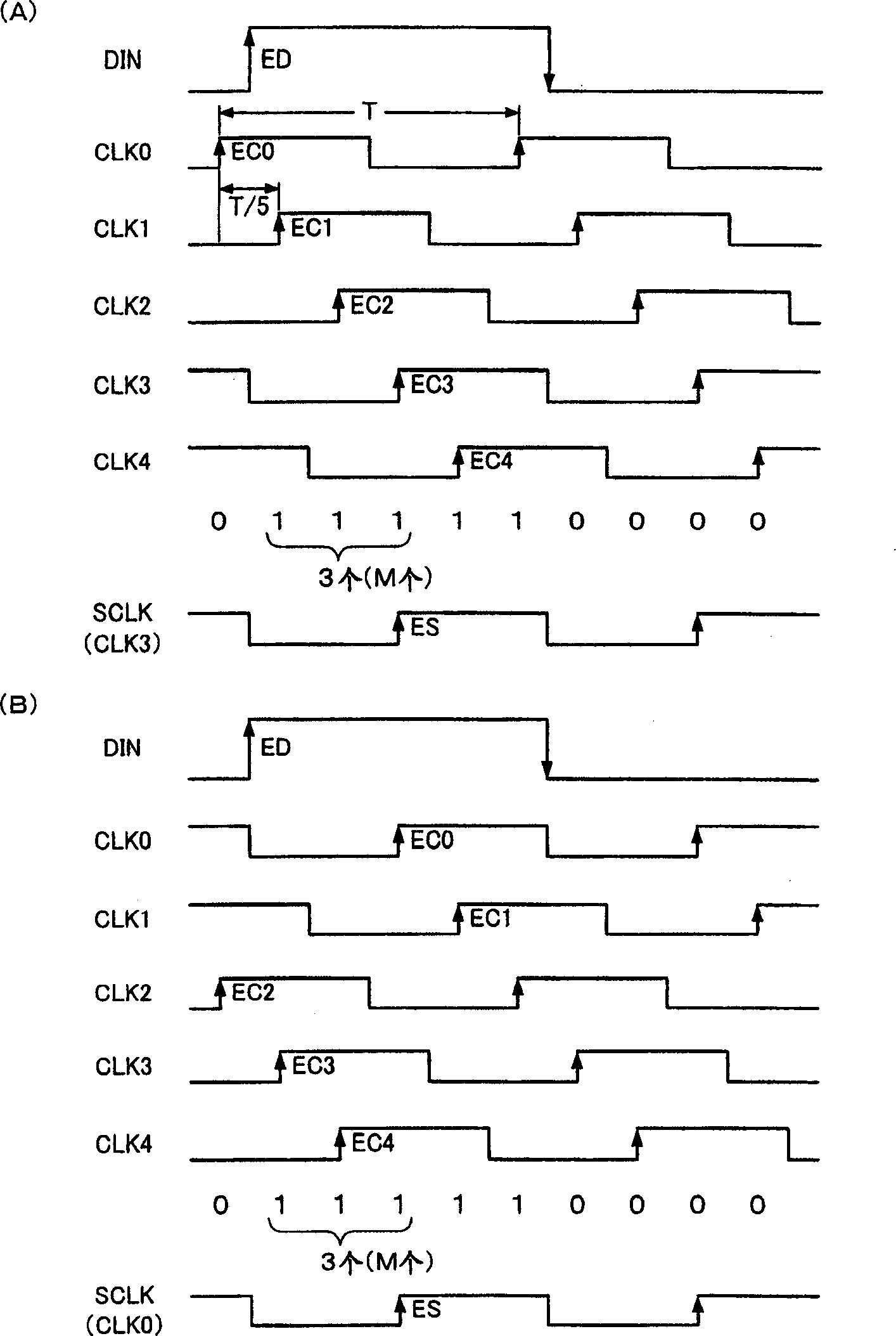
Provided are a sampling clock generation circuit and a data transfer control device make it possible to ensure a set-up time and the like during sampling, while maintaining a high frequency. A sampling clock generation circuit 10 comprises an edge detection circuit 70 detecting between which two edges an edge of data DIN data to be transferred in USB2.0 HS mode is located, the two edges are among edges of clocks CLK0 to CLK4 that have the same frequency but mutually different phases, and a clock selection circuit 72, which selects one of CLK0 to CLK4 based on this edge detection information and outputs the thus-selected clock as a sampling clock SCLK. When the set-up time of a D flip-flop of the edge detection circuit is TS, the hold time is TH, and the period of the clock is T, N is the number of a multi-phase clock is given by: N <=[T / (TS + TH)], (where [X] is the maximum integer that does not exceed X). The clock that has an edge that is shifted by a set number M from an edge of the data DIN is selected as SCLK.

Description

technical field [0001] The present invention relates to a sampling clock generation circuit, a data transfer control device and electronic equipment. Background technique [0002] In recent years, USB (Universal Serial Bus) has attracted attention as an interface standard for connecting personal computers and peripheral devices (electronic devices in a broad sense). The advantage of this USB is that peripheral devices such as mouse, keyboard and printer can be connected with connectors of the same specification. In the past, these devices were connected with connectors of different specifications. . [0003] On the other hand, compared with IEEE1394, which is also emerging as a serial bus interface standard, USB has the problem of slow transmission speed. [0004] Therefore, the USB2.0 standard was established, which attracted attention because it has low-bit compatibility with the previous USB1.1 standard, and at the same time, it can realize a data transfer rate of 480Mb...

Claims


Application Information

Patent Timeline
Patent Type & Authority Applications(China)
IPC IPC(8): G06F13/42G06F1/06G06F13/00H03K3/03H03L7/099H03L7/18H04L7/02H04L7/033
CPCH03L7/0996H04L7/0337H03K3/0322G06F1/06H03L7/18G06F13/00
Inventor 神原义幸
Owner SEIKO EPSON CORP
Learn More