
Hydraulic balancing valve

A hydraulic balance and valve body technology, applied in the field of hydraulic balance valves, can solve problems such as system instability, increased flow resistance, and difficult processing, and achieve the effects of wide application range, low energy loss, and easy processing

Inactive Publication Date: 2002-05-22
卢永松
View PDF1 Cites 53 Cited by
  • Summary
  • Abstract
  • Description
  • Claims
  • Application Information

AI Technical Summary

Problems solved by technology

[0002] In modern engineering machinery, construction machinery and other mechanical equipment, a large number of hydraulic load-bearing systems are used, among which the balance valve is the key hydraulic component of this type of system, and its performance directly affects the performance of the whole machine. The balance valve is mainly composed of a control valve and a main valve. There are two common types: single-stage and pilot-operated. The single-stage main valve and the control valve are connected in parallel, and the pilot-operated main valve and the control valve are nested. The common disadvantage of the performance of all kinds of hydraulic balance valves is that when the hydraulic load-bearing system is descending under load, it is difficult for the spool opening of the balance valve to stabilize at a certain opening size, which will cause low-frequency jitter during the load’s descent, resulting in system failure. It is extremely unstable and seriously affects the safety and reliability of the whole machine. For this reason, a new balance valve is designed, such as the Chinese patent ZL95236163.9 "Combined Manifold Hydraulic Balance Valve". A holding valve is added above the control valve to form a hydraulic integrated block with a common valve body, and a number of damping holes are cleverly set in the hydraulic integrated block, which eliminates low-frequency vibration during the process of lowering heavy objects and enhances safety. make the action more reliable
However, the above defects in this patent are: (1) in the working condition of the weight rising, the flow flows out through the opening of the main valve and the pipeline through the throttle opening of the holding valve, so that the flow resistance increases during the lifting of the weight, Serious energy loss and low efficiency; (2) The damping holes are all fixed holes, so the flow rate can only change with the pressure, and the response is relatively slow; (3) The maximum opening of the main valve cannot be adjusted artificially, which affects its use Scope; (4) Since the patent is designed in one piece, it is difficult to process and almost impossible to implement

Method used


Image

  • Hydraulic balancing valve
  • Hydraulic balancing valve
  • Hydraulic balancing valve

Examples


Embodiment Construction

[0024] The present invention will be further described in detail below in conjunction with the accompanying drawings and embodiments.

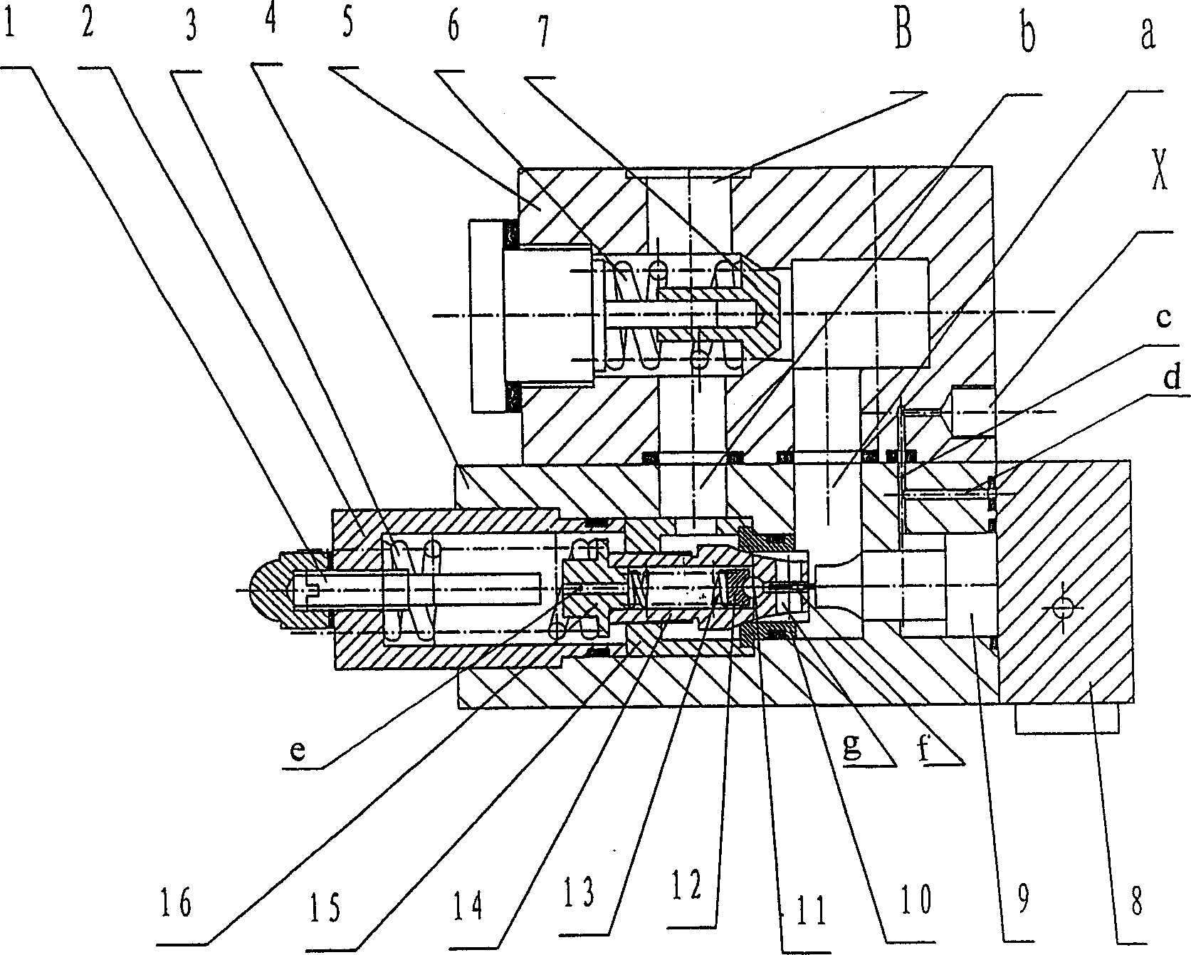
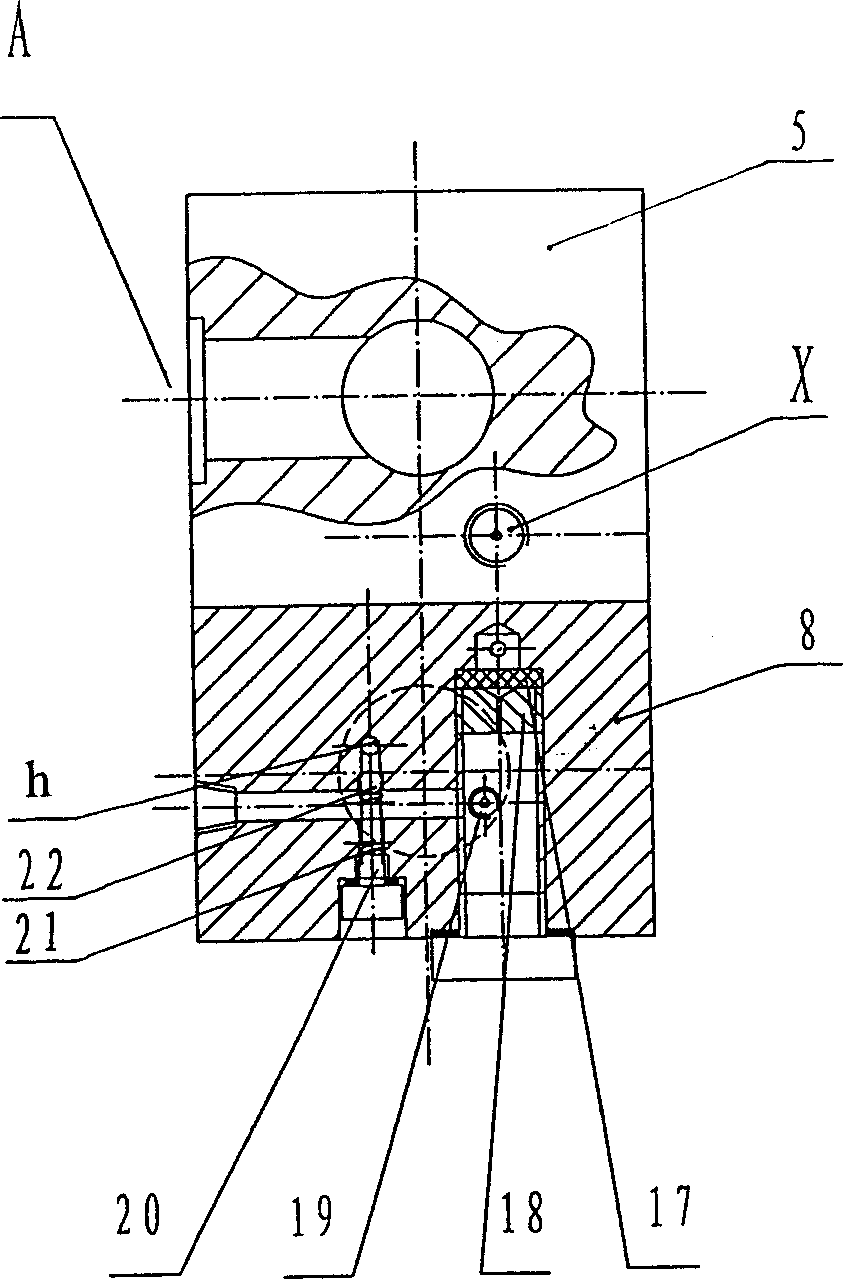
[0025] see figure 1 and figure 2 , the hydraulic balance valve includes a main valve, a pilot valve, a control valve, a valve plate 8 and an adjusting rod 1, the control valve is fixed above the main valve with bolts, the pilot valve is located inside the main valve, and the valve plate 8 is fixed on the main valve with bolts On the right side, the regulating rod 1 is located on the left side of the main valve and is opposite to the main valve core 14 . The control valve includes a control valve body 5, a control spool 7, two front and rear cavities and two main oil ports A, B and control oil port X located on the front, top, and side of the valve body 5, and the control spool 7 passes through the control valve. The spring 6 is connected with the control valve body 5, and the front and rear chambers of the control valve communicate with the...


PUM


Abstract

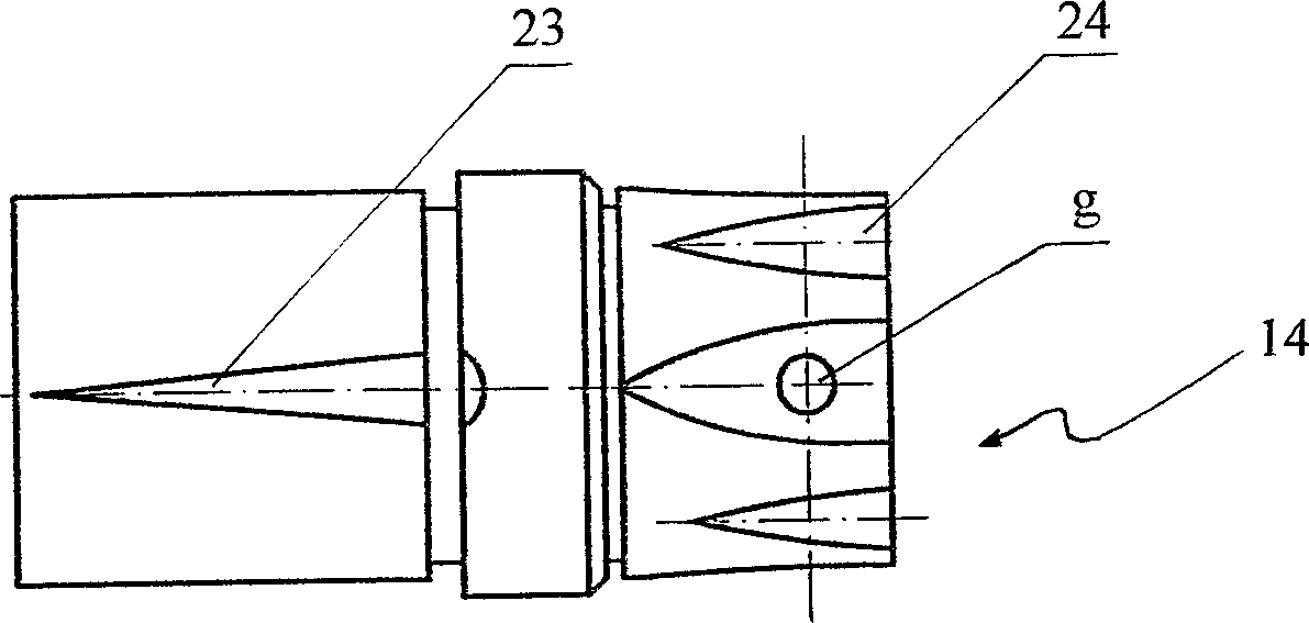
The hydraulic compensation valve comprises main valve, pilot valve and control valve, in which every valve comprises valve body, valve core and its front and rear two cavities, the valve core is connected with valve body by means of spring, pilot valve is placed in the main valve core, the control valve is connected with main valve, said control valve also includes two main oil holes A and B and control oil hole X which are positioned on its valve body, a piston is positioned in front cavity of the main valve, its cavity with rod and cavity without rod are respectively communicated with control oil hole X by means of oil channels of c and d positioned on valve body, the outside of rear end of the main valve core possesses several oblique grooves axially, these oblique grooves are communicated with oil hole B of main valve and rear cavity of main valve, and the rear end of main valve core is equipped with an oil hole e communicated with rear cavity of main valve and rear cavity of pilot valve.

Description

technical field [0001] The invention relates to a valve, in particular to a hydraulic control balance valve used in hydraulic circuits of various open systems ranging from 8 tons to 50 tons. Background technique [0002] In modern engineering machinery, construction machinery and other mechanical equipment, a large number of hydraulic load-bearing systems are used, among which the balance valve is the key hydraulic component of this type of system, and its performance directly affects the performance of the whole machine. The balance valve is mainly composed of a control valve and a main valve. There are two common types: single-stage and pilot-operated. The single-stage main valve and the control valve are connected in parallel, and the pilot-operated main valve and the control valve are nested. The common disadvantage of the performance of all kinds of hydraulic balance valves is that when the hydraulic load-bearing system is descending under load, it is difficult for the ...

Claims


Application Information

Patent Timeline
IPC IPC(8): F15B13/02
Inventor 刘富良卢永松
Owner 卢永松
Learn More