
Rotary dryer

A rotary drying and rotary technology, used in non-progressive dryers, dryers, drying solid materials, etc., can solve problems such as difficulty in implementation, increased cost, and longer drum length.

Inactive Publication Date: 2002-03-06
黄祖汉 +1
View PDF0 Cites 6 Cited by
  • Summary
  • Abstract
  • Description
  • Claims
  • Application Information

AI Technical Summary

Problems solved by technology

[0004] It is said that the structure of the continuous discharge type, in which the horizontal drum is rotated in only one direction to dry the object to be dried, and provided with a spiral discharge mechanism, is suitable for a large number of objects to be dried, but the length of the drum becomes longer. , and an additional discharge device is required, which increases the installation cost
[0005] For the structure of the type in which the drum is inclined in order to facilitate the discharge of the dried object, in this case, when the drying time of the object to be dried is constant, the automation of the discharge process is easy to realize. However, in the form of the object to be dried , When the characteristics are indeterminate or changing, that is, to maintain a certain dryness of the dried object and then perform discharge treatment, the control system will become complicated and difficult to implement
[0006] The type that keeps the drum in a horizontal state to dry the object to be dried, and keeps the drum rotating during discharge and discharges the object to be dried obliquely has the following problems: Although the dryness can be controlled by extending or shortening the drying time according to the shape and characteristics of the object to be dried Certainly, however, since the drum must be tilted during discharge, a device for tilting it is also required
In particular, in the case of a drying device in which hot air is sent not only from the inside of the drum but also from the outside, the mechanism for tilting must be heat-resistant, which increases the cost of the device.

Method used


Image

  • Rotary dryer
  • Rotary dryer
  • Rotary dryer

Examples


Embodiment Construction

[0017] Hereinafter, the device related to the present invention will be described in detail with reference to the drawings of the embodiments.

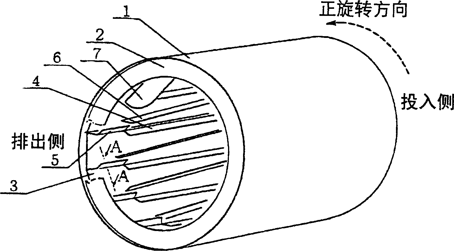
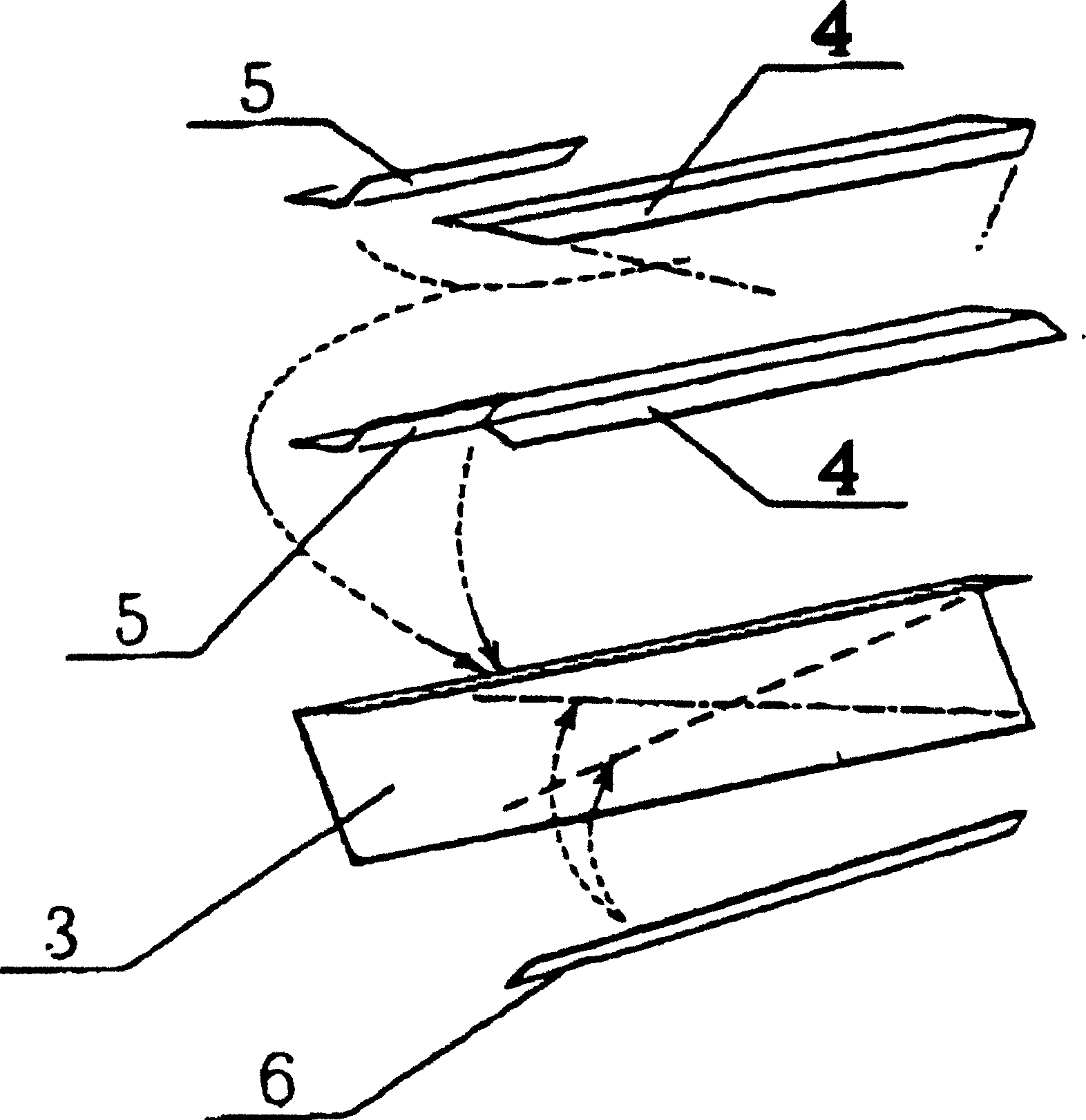
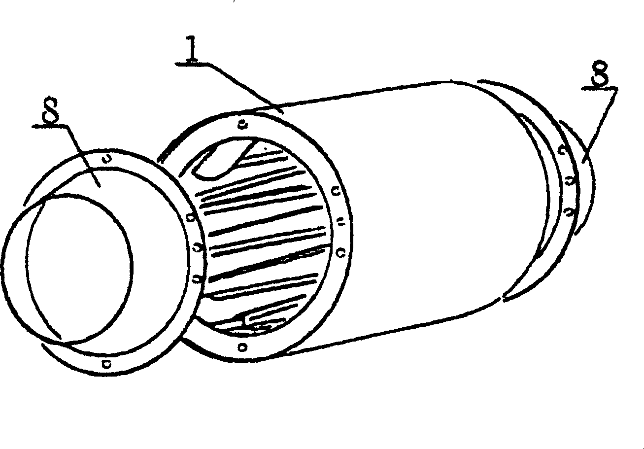
[0018] Figure 1 to Figure 3 Examples of inventions corresponding to claims 1 to 4 of the present invention are shown. At both ends of the outer cylinder (1) of the drum, the end plates (2) welded thereon are fixed, and further, a spacer (3) with a U-shaped or レ-shaped cross section is installed on the inner side of the outer cylinder. Both ends are fixed by end plates. On the spacer, a lifter (4) for forward rotation and a lifter (5) for reverse rotation are installed, and further, transfer ribs (6) are installed as required. Each part may be attached by any heat-resistant and firm method such as riveting, welding, or brazing. The material of each component is selected according to the characteristics of the object to be dried, especially the corrosion and heat resistance.

[0019] Simultaneously, the cross-section of the separat...


PUM


Abstract

A rotary dryer, wherein a mechanism having a discharging action in reverse rotation is provided inside a drying drum and the drying drum is rotated reversely in a process where drying substance is discharged, and also the dried object and drying substance are prevented from being dispersed at the time of charging and discharging them, a plurality of the drums are provided continuously and a specified relation is given between the rotating direction, time, and speed of each drum so as to reduce an operational play of each drum in order to increase the efficiency of the entire dryer.

Description

technical field [0001] The present invention relates to a device that not only makes the dryness of the dried object uniform, but also discharges the dried object simply and accurately. Background technique [0002] For a drying device that puts the object to be dried into a drying drum (hereinafter referred to as: drum), and sends hot air to dry it while rotating the drum, according to the shape and characteristics of the object to be dried, such as fluidity, vulnerability, specific gravity, particle size, The moisture content, the speed of drying, the amount of the object to be dried, etc. determine the diameter and length of the drum, and design the most suitable drying drum. For the previous rotary drying device, the following structures are used: such as Figure 4 As shown, the cylindrical outer drum (11) equipped with a conveying lifter (16) is placed horizontally and rotates in only one direction. A type of structure in which a screw type discharge mechanism is provi...

Claims


Application Information

Patent Timeline
Patent Type & Authority Applications(China)
IPC IPC(8): F26B3/24F26B11/02F26B11/04F26B17/32F26B25/00
CPCF26B11/0477F26B11/026F26B11/04
Inventor 黄祖汉
Owner 黄祖汉
Learn More