
Gantray crane having circulating trolleys

A cyclic, crane technology, applied in the direction of trolley cranes, cranes, load hanging elements, etc., can solve the problems of delayed container transportation, difficult container positioning, and reduced loading and unloading speed and efficiency.

Inactive Publication Date: 2002-02-27
CREA-TECH
View PDF0 Cites 11 Cited by
  • Summary
  • Abstract
  • Description
  • Claims
  • Application Information

AI Technical Summary

Problems solved by technology

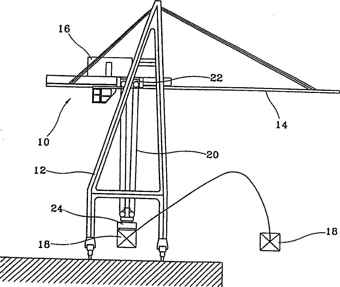
[0004] However, this conventional tower crane lowers the lashing beam 24 to pick up the container while the crane 22 moves along the jib 14, so that some time is required for the lashing beam 24 to be positioned precisely on the The top of the container 18 to be shipped
Therefore, the transportation of the container is delayed
In addition, the lashing beam 24 is suspended by the steel rope 20 even when it picks up the container and transfers it to the loading / unloading location, so the container may sway due to the movement of the crane 22
Therefore, it is difficult to locate the container at a precise location, which greatly reduces the speed and efficiency of loading and unloading

Method used


Image

  • Gantray crane having circulating trolleys
  • Gantray crane having circulating trolleys
  • Gantray crane having circulating trolleys

Examples


Embodiment Construction

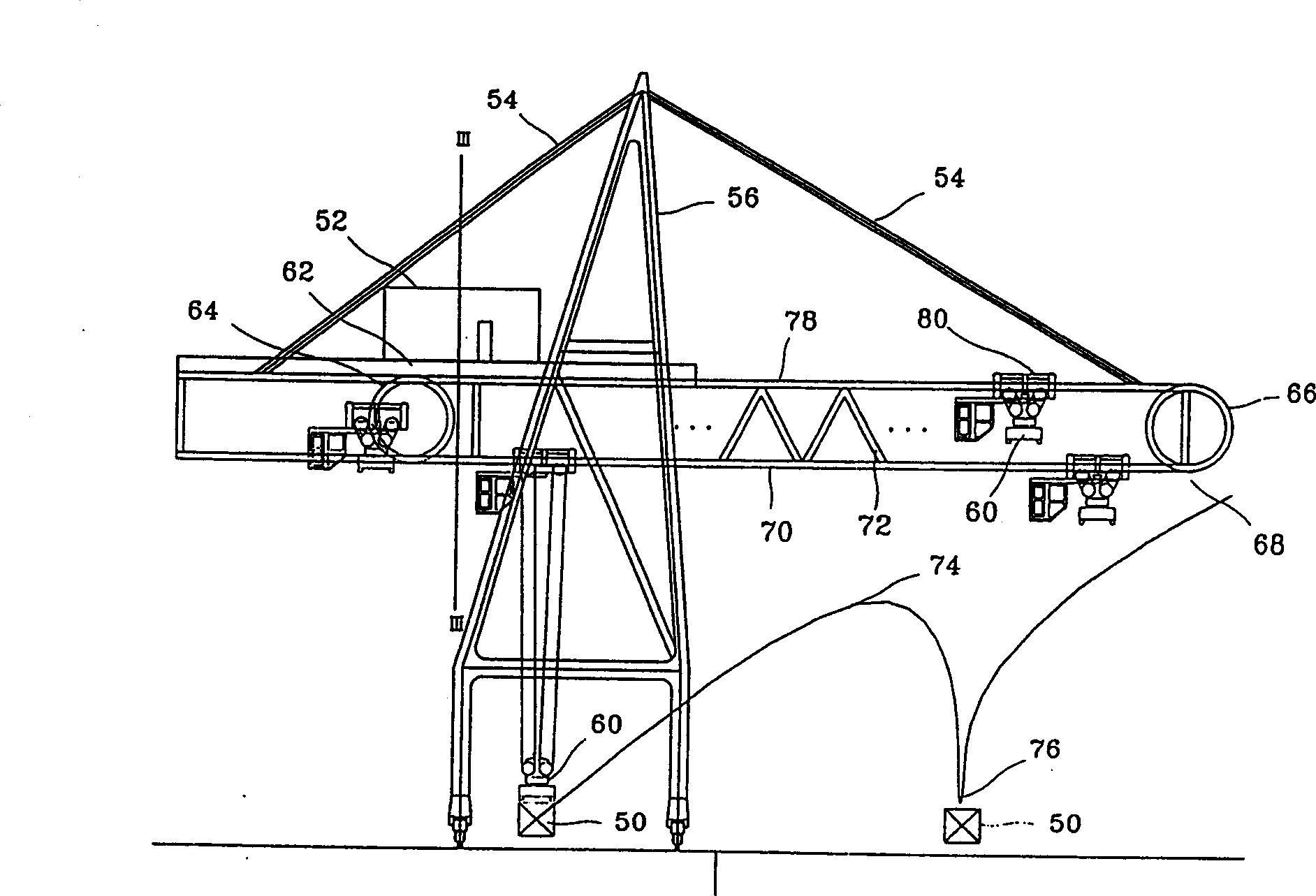
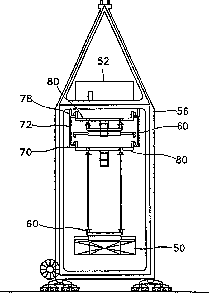
[0015] refer to figure 2 , shows the vertical circulation tower crane invented by the applicant, the first boom 70 is installed parallel to the ground at the predetermined height of the movable main tower column 56, and the second boom 78 is installed first A predetermined distance above the heavy arm 70 and parallel thereto. The tie bar 54 is connected to the second boom 78 to prevent the first and second booms 70 and 78 from sagging, and the first and second booms 70 and 78 are connected to each other by the connecting member 72, thereby forming a truss structure .

[0016] A plurality of cranes 80 having lashing beams 60 are movably mounted on the first and second booms 70 and 78 . The first and second circulating boom attachment devices 66 and 64 are mounted on the respective ends of the first and second booms 70 and 78 so that the crane 35 can move between the first and second booms 70 and 78. Cycle between runs. The machinery room 52 for controlling the first and se...


PUM


Abstract

A Gantry crane having circulating trolleys (102), including a movable main tower pillar (56), a circulating boom, at least one trolley (102), at least one spreader (60), two hoists (106, 108), and a hook (116). The circulating boom is installed on the main tower pillar (56). The trolley (102) is installed to be capable of circulating along the circulating boom (100). The spreader (60) can be attached to and detached from the lower surface of the trolley (102), is combined with the trolley (102) when the trolley (102) moves, and is separated from the trolley (102) and descends to pick up a container (50). Two hoists (106, 108) are installed to be capable of moving along the circulating boom (100), each having a hoist motor (110) and a hoist wheel (112). The hook (116) is connected to the hoist motor (110), and combined with the spreader (104) by descending while vertically passing through the trolley (102) and is separated from the spreader (104) by ascending, so that the hook (116) descends with the spreader (104) combined with the hook (116) in order to pick up a container (150).

Description

technical field [0001] This invention relates to tower cranes and in particular to tower cranes with circulating cranes. Background technique [0002] Freight transportation using containers was started by Sea-Land Service Co. in 1957, and has been widely developed since Matson Navigation Co. started container transportation along the Atlantic Ocean in 1958. At present, except for liquid and powder cargo, 80% or more of cargo transportation is carried in containers, and it is estimated that this percentage will be even higher in the future. With the increasing application of containers, due to the increase in drive motor capacity, the development of cranes and hanging beams, and the introduction of automatic control systems, etc., the handling capacity of container cranes has also been improved. [0003] Such as figure 1 As shown, the jib 14 in the conventional tower crane is horizontally coupled to the main tower column 12, and the crane 22 including the machine room 16 a...

Claims


Application Information

Patent Timeline
IPC IPC(8): B66C13/00B66C19/00
CPCB66C19/002B66C13/00
Inventor 韩万烨孙承尧
Owner CREA-TECH
Learn More