
Large-amplitude centrifugal vibrating grinder

A vibrating mill and large-amplitude technology, which is applied in grain processing and other directions, can solve problems such as multi-axis eccentricity mutual interference, high equipment precision requirements, and impact on equipment life, so as to improve grinding ability, improve operating process performance, and improve The effect of service life

Inactive Publication Date: 2002-02-13
胡传东
View PDF1 Cites 3 Cited by
  • Summary
  • Abstract
  • Description
  • Claims
  • Application Information

AI Technical Summary

Problems solved by technology

But there are different shortcomings. For example, the turning rod mill uses more than three turning shafts to support a barrel for eccentric circular movement. The maximum amplitude is 15mm (one-way). The equipment requires high precision and is difficult to manufacture. The mass of the vibration is large, it is easy to produce multi-axis eccentric mutual interference, which affects the life of the equipment, and it is limited to use long rods as grinding media
The vibrating grinder is generally a double-barrel structure, driven by two synchronous motors, the barrel is supported by multiple gas springs, and the vibration is generated by the vibration of the eccentric block. The amplitude is ≤ 6mm (one-way). Due to the small amplitude, only more can be installed. Dielectric ball, so the equipment is large and consumes a lot of energy

Method used


Image

  • Large-amplitude centrifugal vibrating grinder
  • Large-amplitude centrifugal vibrating grinder
  • Large-amplitude centrifugal vibrating grinder

Examples


Embodiment 1

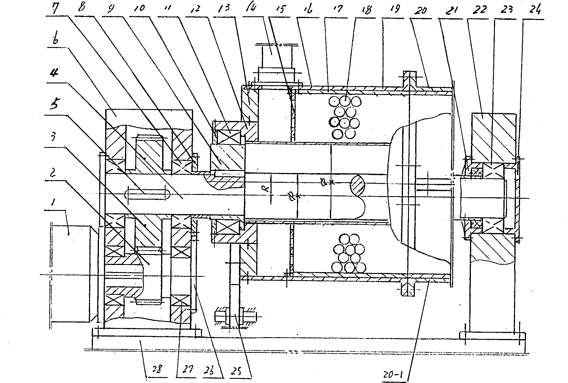
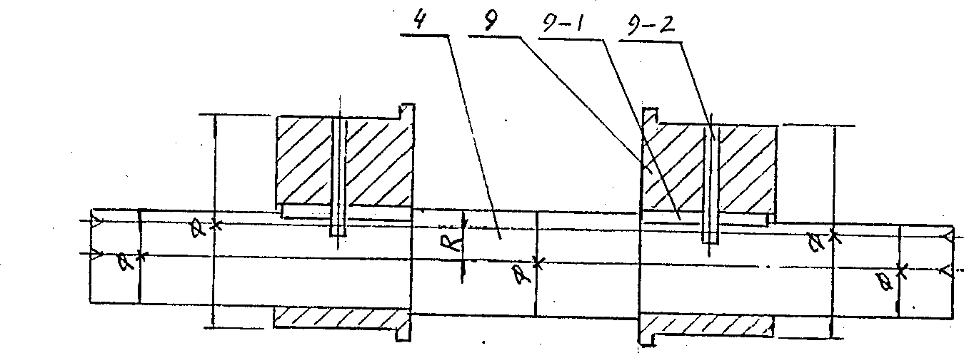
[0036]Embodiment 1, open-circuit large-amplitude centrifugal vibratory mill, there can be one barrel or multiple barrels, each barrel is equipped with an eccentric main shaft and a set of gear rotation system, and the whole mill is driven by the motor 1, The motor drives the main gear shaft 2 to drive the eccentric main shaft gear 3, the eccentric main shaft gear and the eccentric main shaft 4 rotate synchronously, and the eccentric part bearing 11 of the eccentric main shaft pushes the integral barrel or the three-section barrel to make large-amplitude centrifugal circular vibration. Because the support rod 25, the square key 29, and the support rod system of the bearing roller 30 are installed on the side of the barrel, the rotation of the barrel is limited, and it can only vibrate up, down, left, and right in a centrifugal circle. The ball 18 also vibrates accordingly, the medium ball revolves along the wall of the barrel and rotates at high speed, and the material is ground...

Embodiment 2

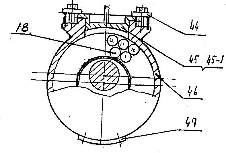
[0037] Embodiment 2, closed-circuit large-amplitude centrifugal vibratory mill, the barrel can also be one or more, its structure and movement principle are the same as in Example 1, except that the inlet and outlet of the barrel are the same mouth, and the timed feeding Material, timed discharge. On the upper part of the material barrel is a grid-shaped structure of the material inlet and outlet 45, the material inlet and outlet cover 45-1 is arranged on the material inlet and outlet, and the medium ball inlet and the cover 47 are located on the lower part of the material barrel. Airtight, so it is a closed barrel. When in use, first open the sealing cover of the medium ball inlet, put the medium ball 18 into the closed barrel 46, then seal it, then open the sealing cover of the material opening, load a certain amount of material, seal it again, and position the support rod 25 On the bearing roller 30, you can start grinding. After grinding, open the closed cover of the mat...


PUM


Abstract

The centrifugal vibrating grinder has medium balls to beat and crush material inside one material cylinder in centrifugal circular vibration. It has large amplitude of centrifugal circular vibration up to 50 mm, small vibrated mass, great beating force of the medium balls, and thus high grinding fineness, high production efficiency, long equipment service life and improved technological operationperformance. It has one bearing rod assembly penetrating the eccentric shaft of the material cylinder and limiting the rotation motion of the material cylinder as well as lining arc board, special partition board, material feeding and discharging device, balanced arrangement, etc. The present invention is suitable for both large scale production in mine, building industry, etc. and small scale production.

Description

technical field [0001] The invention relates to material crushing machinery, especially the field of vibration mills. Background technique [0002] With the development of production, especially the needs of mining and building materials industries, a large part of the ball mills that were widely used in the past have been replaced by various types of vibration mills. Currently, there are vibration mills and swing rod mills. But there are different disadvantages. For example, the turning rod mill uses more than three turning shafts to support a barrel to perform eccentric circular movement. The maximum amplitude is 15mm (one-way). The equipment requires high precision and is difficult to manufacture. The vibration mass is large, it is easy to produce multi-axis eccentric mutual interference, which affects the life of the equipment, and it is limited to using long rods as grinding media. The vibrating grinder is generally a double-barrel structure, driven by two synchronous ...

Claims


Application Information

Patent Timeline
Patent Type & Authority Applications(China)
IPC IPC(8): B02C17/14
Inventor 胡传东
Owner 胡传东
Learn More