
Printed circuit board for mounting a quad flat package IC, method of soldering a quad flat package IC, and air conditioning apparatus with such a printed circuit board

A technology of printed circuit board and welding method, applied in the direction of assembling printed circuits with electrical components, printed circuits connected with non-printed electrical components, printed circuits, etc., can solve problems such as short circuits, reduce tin bridges, increase manual labor Correction of work, effect of preventing solder short circuit

Active Publication Date: 2007-07-25
MITSUBISHI ELECTRIC CORP
View PDF2 Cites 2 Cited by
  • Summary
  • Abstract
  • Description
  • Claims
  • Application Information

AI Technical Summary

Problems solved by technology

However, the solderability of lead-free solder is worse than that of lead-containing eutectic solder that has been used in the past. For this reason, solder failure occurs between pin terminals such as 4-pin flat package ICs. resulting short circuit

Method used


Image

  • Printed circuit board for mounting a quad flat package IC, method of soldering a quad flat package IC, and air conditioning apparatus with such a printed circuit board
  • Printed circuit board for mounting a quad flat package IC, method of soldering a quad flat package IC, and air conditioning apparatus with such a printed circuit board
  • Printed circuit board for mounting a quad flat package IC, method of soldering a quad flat package IC, and air conditioning apparatus with such a printed circuit board

Examples


Embodiment Construction

[0029] Embodiment 1

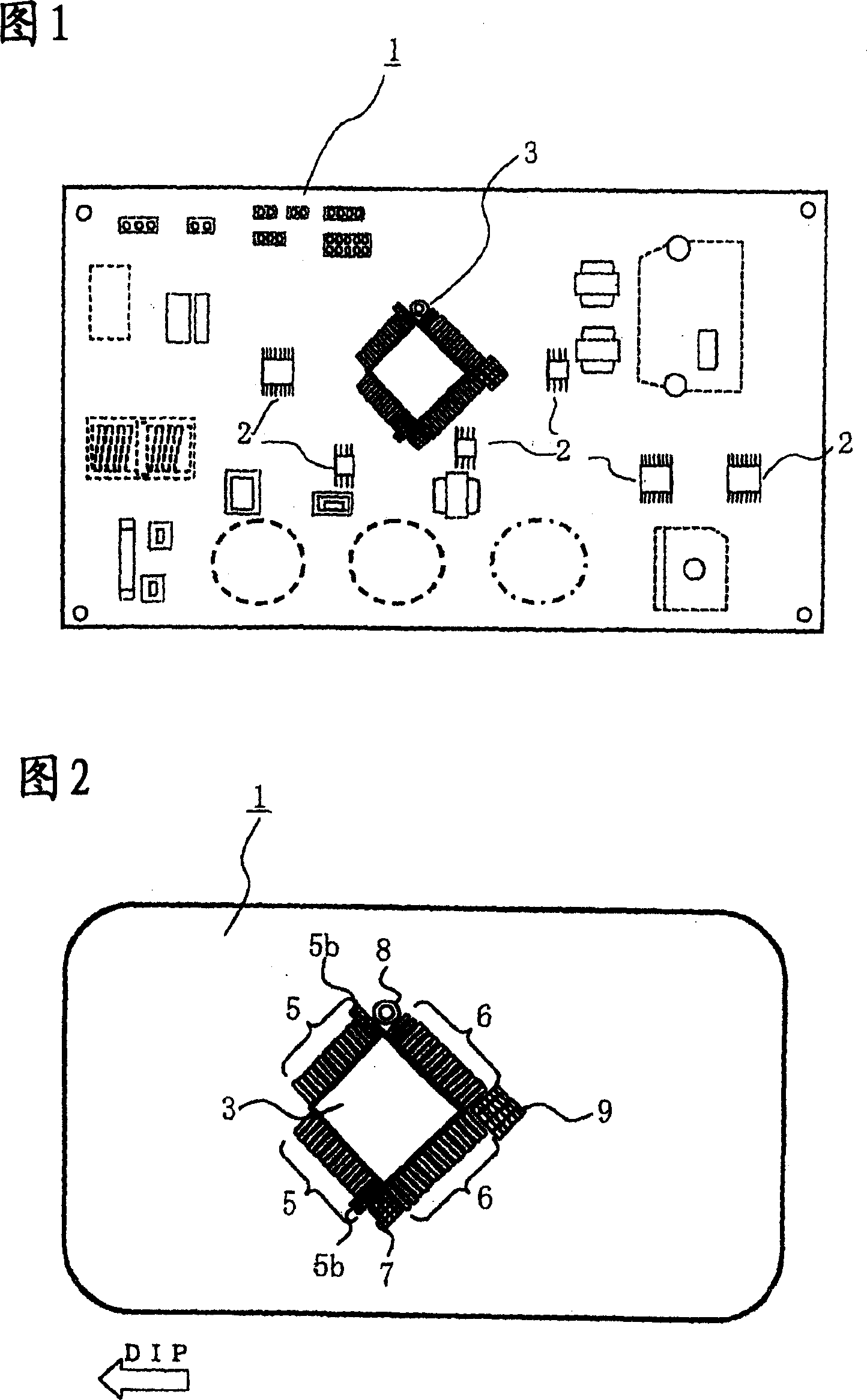
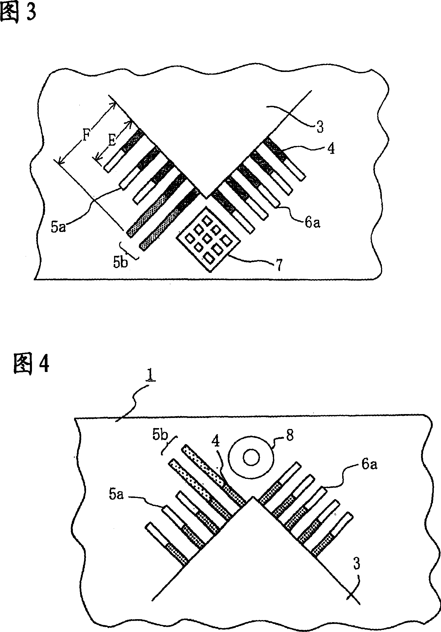
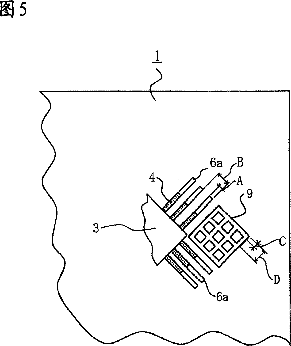
[0030] Next, a 4-direction pin flat package IC mounted printed wiring board according to Embodiment 1 of the present invention will be described with reference to FIGS. 1 to 4 . Here, the plan view of FIG. 1 shows a schematic configuration of a 4-direction pin flat package IC mounting printed wiring board according to Embodiment 1 of the present invention viewed from the back, and the plan view of FIG. 2 shows Embodiment 1 of the present invention. The 4-direction pin flat package IC, the enlarged plan view of the main part of Fig. 3 shows the front land group and the rear of the printed wiring board on which the 4-direction pin flat package IC according to Embodiment 1 of the present invention is mounted. The relationship on one side of the land group, the enlarged plan view of the main part of FIG. 4 shows another difference between the front land group and the rear land group of the 4-direction pin flat package IC mounting printed wiring board accordin...


PUM


Abstract

Where a quad-directional-lead flat-package IC is soldered using a flow-soldering bath, particularly, for example, when the inter-lead pitch is narrow, there has been a problem in that solder bridges are generated. In the present invention, a printed circuit board is configured so that a quad-directional-lead flat-package IC is mounted thereon, and attached by soldering using a flow-soldering bath; forward soldering land groups are angled with respect to the soldering advance direction so that with respect to the flow soldering direction a corner of the quad-directional-lead flat-package IC will be at the head end and a diagonally opposing corner will be at the tail end; a solder-drawing land having a lattice form is provided in either one of the spaces between each forward soldering land group and its adjacent rearward soldering land group, and / or in the tail-endmost portion of the rearward soldering land groups; and an eyelet is provided in the other one of the spaces.

Description

technical field [0001] The present invention relates to mounting a printed wiring board of a 4-direction pin flat package IC by soldering using a jet soldering bath. Background technique [0002] Generally speaking, printed circuit boards are increasingly required to be finer in the mounting density of components, so board assembly of narrow-pitch 4-direction pin flat package ICs and the like has become indispensable. On the other hand, the practical use of lead-free solders in consideration of environmental issues has also become an urgent task. However, the solderability of lead-free solder is worse than that of lead-containing eutectic solder that has been used in the past. For this reason, solder failure occurs between pin terminals such as 4-pin flat package ICs. resulting in a short circuit. [0003] In the past, in this printed wiring board, in order to prevent the occurrence of solder bridges, the lateral solder-drawing lands have substantially the same width on th...

Claims


Application Information

Patent Timeline
Patent Type & Authority Patents(China)
IPC IPC(8): H05K1/18H05K1/02H05K3/34F24F11/00H05K1/11H05K3/42
CPCH05K2201/09681H05K2203/046H05K3/42H05K3/3468H05K2201/094H05K2201/09781H05K2201/10689H05K1/111Y02P70/50
Inventor 三浦刚福岛宽信森秀树
Owner MITSUBISHI ELECTRIC CORP
Learn More