
Thin film transistor array base plate and patching method thereof

A thin film transistor and array substrate technology, applied in the field of active element array substrate and its repair, can solve the problems of increasing the number of dark spots on the panel, affecting the display quality, etc., and achieve the effect of improving the process yield and ensuring normal operation.

Active Publication Date: 2007-07-04
AU OPTRONICS CORP
View PDF9 Cites 0 Cited by
  • Summary
  • Abstract
  • Description
  • Claims
  • Application Information

AI Technical Summary

Problems solved by technology

However, this approach will relatively increase the number of dark spots on the panel, thus affecting the display quality

Method used


Image

  • Thin film transistor array base plate and patching method thereof
  • Thin film transistor array base plate and patching method thereof
  • Thin film transistor array base plate and patching method thereof

Examples


Embodiment Construction

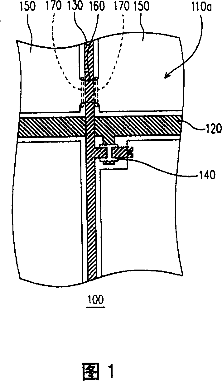
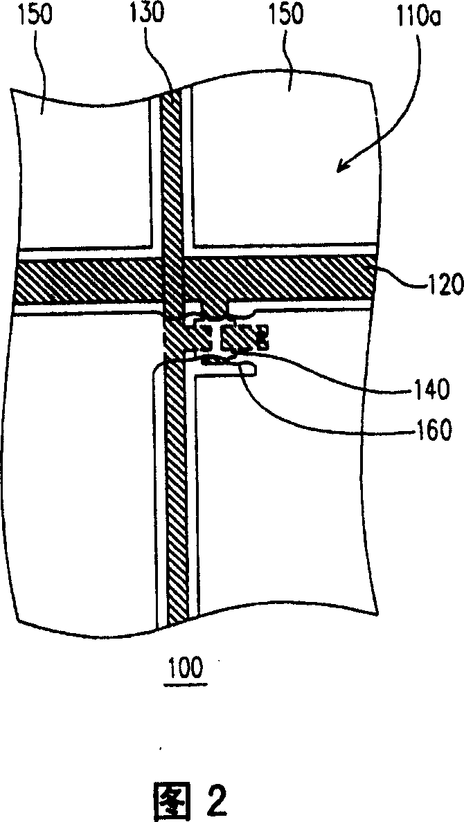
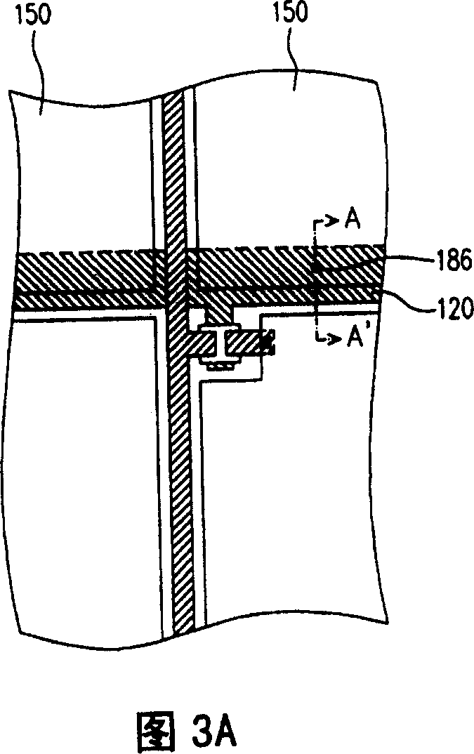
[0029]Please refer to FIG. 1 , which shows a schematic diagram of a thin film transistor array substrate according to a preferred embodiment of the present invention. The thin film transistor array substrate 100 includes, for example, a substrate 110 (shown in FIG. 3B ), a plurality of scanning lines 120 , a plurality of data lines 130 , a plurality of thin film transistors 140 and a plurality of pixel electrodes 150 . Wherein, the scan wires 120 and the data wires 130 are respectively disposed on the substrate 110, and a plurality of pixel regions 110a are divided on the substrate. The thin film transistor 140 is correspondingly disposed in the pixel area 110 a and driven by the scan wiring 120 and the data wiring 130 . In addition, the pixel electrode 150 is correspondingly disposed in the pixel region 110 a and is electrically connected to the corresponding thin film transistor 140 , and the material of the pixel electrode 150 is, for example, a transparent conductive mater...


PUM

PropertyMeasurementUnit
wavelengthaaaaaaaaaa

Abstract

A fixing method for thin film transistor array base plate is to remove the remains between the picture elements electrodes to avoid the abnormal conducting between adjacent electrode because of remains and to remove the particles which can results the leakage of stored capacitor or part of picture element electrodes above the leakage to ensure the normal operation of stored capacitor. The fixing method of thin film transistor array base plate can provide accurate control and micro adjusting to the energy to be fixed and to increase the preparation quality of thin film transistor array base plate.

Description

technical field [0001] The present invention relates to an active element array substrate (Thin Film Transistor array, TFT array) and its repair method, and in particular to a thin film transistor array capable of greatly improving the yields of repair process Substrates and methods of repairing them. Background technique [0002] With the substantial improvement of computer performance and the high development of Internet and multimedia technology, most of the transmission of image information has been converted from analog to digital transmission. In order to adapt to the modern life style, the volume of video or image devices is becoming thinner and thinner day by day. The traditional cathode ray tube (Cathode Ray Tube, CRT) display has been monopolizing the display market in recent years because of its excellent display quality and economy. However, for the environment where individuals operate most terminals / display devices on the table, or from the perspective of env...

Claims


Application Information

Patent Timeline
Patent Type & Authority Patents(China)
IPC IPC(8): G02F1/1368G02F1/1333G02F1/133G02F1/136H01L29/786
Inventor 来汉中
Owner AU OPTRONICS CORP
Learn More