Method for repairing thin-film transistor array substrate and thin film removing method

A technology of thin film transistors and array substrates, which is applied in the repair of thin film transistor array substrates and the removal of thin films. It can solve the problems of affecting display quality and increasing the number of dark spots on the panel, so as to improve the process yield and ensure normal operation.

Active Publication Date: 2008-12-10
AU OPTRONICS CORP
View PDF3 Cites 0 Cited by
  • Summary
  • Abstract
  • Description
  • Claims
  • Application Information

AI Technical Summary

Problems solved by technology

However, this approach will relatively increase the number of dark spots on the panel, thus affecting the display quality

Method used


Image

  • Method for repairing thin-film transistor array substrate and thin film removing method
  • Method for repairing thin-film transistor array substrate and thin film removing method
  • Method for repairing thin-film transistor array substrate and thin film removing method

Examples


Embodiment Construction

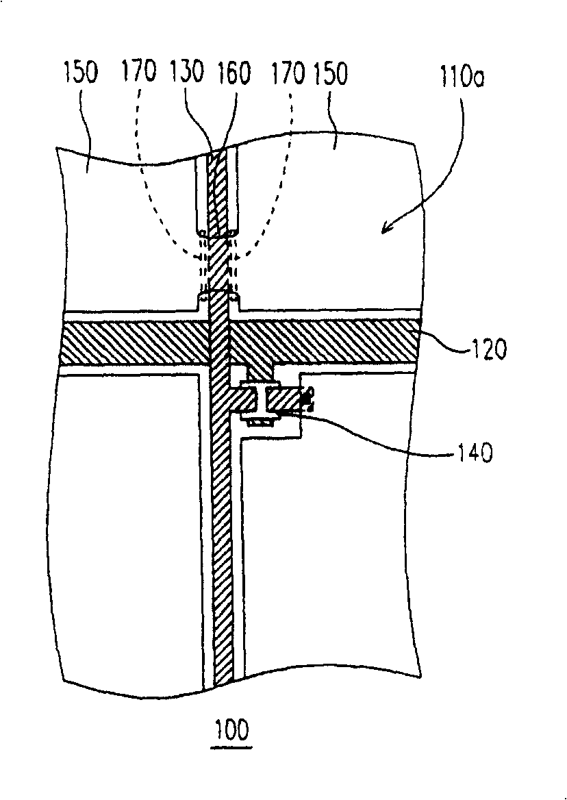
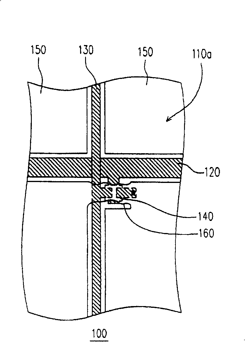
[0030] Please refer to figure 1 , which shows a schematic diagram of a thin film transistor array substrate according to a preferred embodiment of the present invention. The thin film transistor array substrate 100 includes, for example, a substrate 110 (shown in Figure 3B Middle), a plurality of scanning lines 120 , a plurality of data lines 130 , a plurality of thin film transistors 140 and a plurality of pixel electrodes 150 . Wherein, the scan wires 120 and the data wires 130 are respectively disposed on the substrate 110, and a plurality of pixel regions 110a are divided on the substrate. The thin film transistor 140 is correspondingly disposed in the pixel area 110 a and driven by the scan wiring 120 and the data wiring 130 . In addition, the pixel electrode 150 is correspondingly disposed in the pixel region 110 a and is electrically connected to the corresponding thin film transistor 140 , and the material of the pixel electrode 150 is, for example, a transparent co...


PUM

PropertyMeasurementUnit
wavelengthaaaaaaaaaa

Abstract

A method for repairing base plate of thin film transistor array includes exerting a pulse light beam with pulse width of 1 / 20-1 / 4 second on residue between pixel electrodes at said base plate in order to remove off at least a partial residue and to make those pixel electrodes at two sides of said residue be electrically insulated.

Description

[0001] This application is a divisional application with application number ZL2004100422758. The filing date of the original application is April 28, 2004, and the title of the invention is "Thin Film Transistor Array Substrate and Its Repair Method". technical field [0002] The present invention relates to a thin film transistor array substrate (Thin Film Transistor array, TFT array) repair method and thin film removal method, and in particular to a method that can greatly improve the yield of the repair process (yields of repair process) ) The method for repairing the thin film transistor array substrate and the method for removing the thin film. Background technique [0003] With the substantial improvement of computer performance and the high development of Internet and multimedia technology, most of the transmission of image information has been converted from analog to digital transmission. In order to adapt to the modern life style, the volume of video or image devic...

Claims


Application Information

Patent Timeline
Patent Type & Authority Patents(China)
IPC IPC(8): H01L21/84H01L21/768H01L27/12H01L23/522G02F1/136
Inventor 来汉中
Owner AU OPTRONICS CORP
Why Eureka
Try Eureka