Reciprocating compressor

A compressor and reciprocating technology, applied in the direction of liquid variable displacement machinery, mechanical equipment, engine components, etc., can solve problems such as valve damage, and achieve the effect of reducing operating stress, reducing pressure, and reducing contact area

Inactive Publication Date: 2007-04-25
CARRIER CORP
View PDF3 Cites 0 Cited by
  • Summary
  • Abstract
  • Description
  • Claims
  • Application Information

AI Technical Summary

Problems solved by technology

If the operating stress significantly exceeds the fatigue strength of the valve, the valve will fail

Method used


Image

  • Reciprocating compressor
  • Reciprocating compressor
  • Reciprocating compressor

Examples


Embodiment Construction

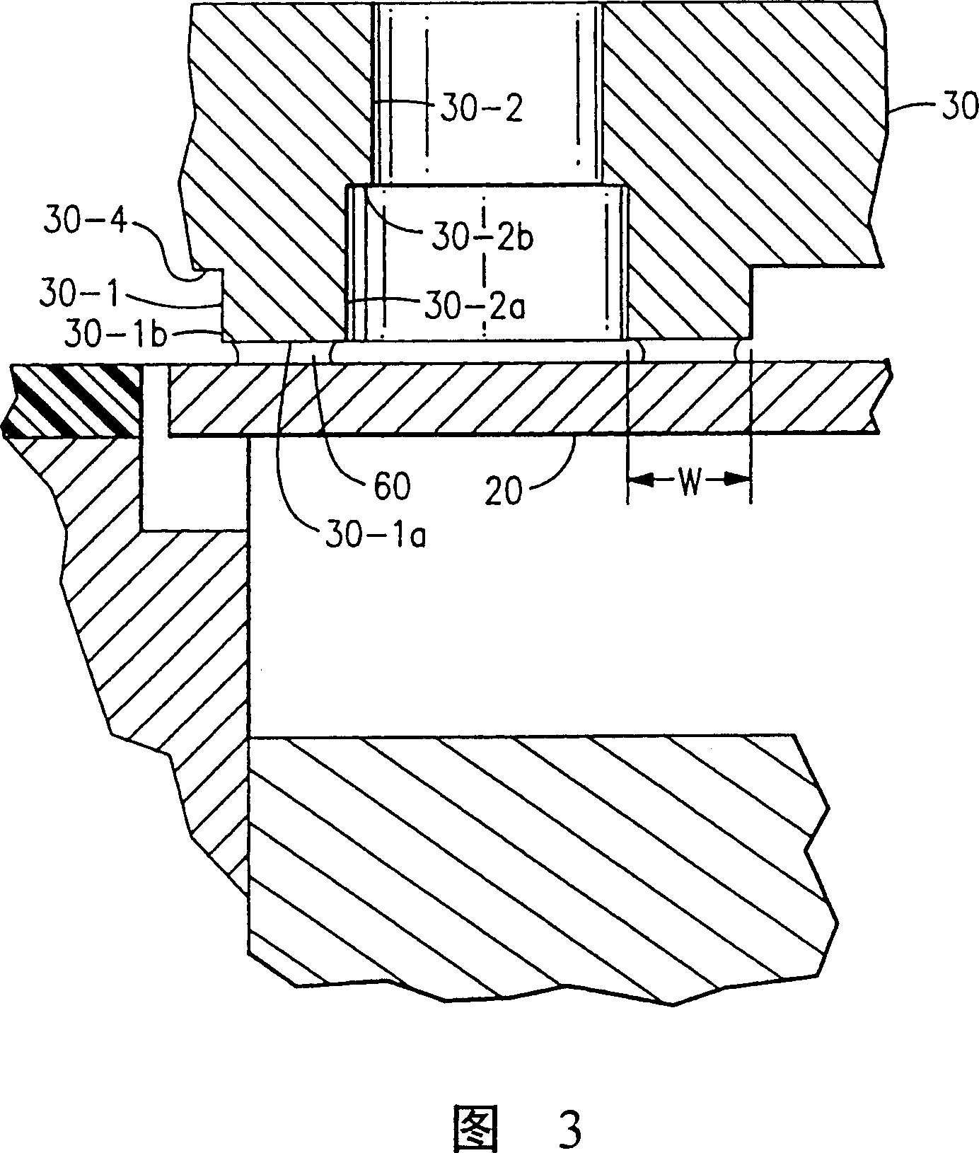
[0023] In Figs. 1 and 2, reference numeral 10 generally denotes a reciprocating compressor. As with conventional compressors, compressor 10 has a suction valve 20, shown as a reed valve, and a discharge valve 50, and a piston 42 located in a bore or cylinder 40-3. The discharge valve 50 has a valve pad 51 which limits the movement of the valve 50 and is generally designed to dissipate the opening force applied to the valve 50 over its entire opening movement through the discharge passage 30-5. In the case of the suction valve 20, its valve tip 20-1 engages with a flange 40-1 in a groove 40-2 in the crankcase 40 which acts as a valve stop. Flange 40-1 engages after 0.1 inches of opening movement to reduce clearance volume and further opening movement by flexing of valve 20, as shown in phantom in FIG. Specifically, valve 20 initially moves as a cantilever until valve tip 20-1 engages flange 40-1 and then bends in the form of a beam supported at both ends. As shown in phantom ...


PUM


Abstract

The seat of a suction valve of a reciprocating compressor is modified to limit the radial extent and thereby the area in which an annular oil film can be established between the valve and the valve seat. The preferred radial extent of the seating surface is 0.014 to 0.018 inches and the preferred ratio of the area of the suction valve seat to the passage therethrough is in the range of 13% to 25%.

Description

technical field [0001] The present invention relates to a reciprocating compressor having a cylinder with a piston therein, a suction valve and a valve plate with an integral suction valve seat lubricated by oil between said suction valve and valve seat An oil film is formed between them. Background technique [0002] In a positive displacement compressor employing a suction valve and a discharge valve, there are similarities and differences between the two valves. These valves are usually of the same general type. Each valve is normally closed and opens due to a pressure differential across the valve in an opening direction. The valve can be made of elastic material and provide its own support deflection, or a split spring can be used. Since the suction valves open into the compression chamber / cylinder, they are usually without valve pads to reduce clearance volume so that the deflection of the valve is practically unrestricted. Discharge valves usually have some sort o...

Claims


Application Information

Patent Timeline
IPC IPC(8): F04B53/10F04B39/10
CPCF04B39/1073Y10T137/4358Y10T137/7892F16K15/14
Inventor M·J·多默B·A·弗雷泽W·P·比格尔P·F·凯多K·D·韦塞尔斯
Owner CARRIER CORP
Why Eureka
Try Eureka