


Quick Research
Generate reliable direction feasibility study reports for your R&D in just a few steps.

Technical Q&A
Discover and master advanced knowledge NOW. Basics, ideas, possibilities, all at once.

Find Solutions
As an expert in R&D theories, this can generate solutions to your technical problems instantly.

Evaluate Feasibility
Analyze your overall solution with one click, know your potential R&D risks in advance.

Monitor Landscape
Get weekly tech updates, stay abreast of the latest tech innovations and key insights.
Soldering structure and soldering method for machinable seal structual parts
A sealing member, machinability technology, applied in welding equipment, engine components, blade support components, etc., can solve problems such as the inability to play the function of honeycomb seals and the severe loss of turbine rotor blades, achieve high precision and reliable guarantee, The effect of suppressing penetration
- Summary
- Abstract
- Description
- Claims
- Application Information
AI Technical Summary
Problems solved by technology
Method used
Image

Examples
Embodiment Construction
[0031] An embodiment of the present invention will be described below with reference to the drawings.
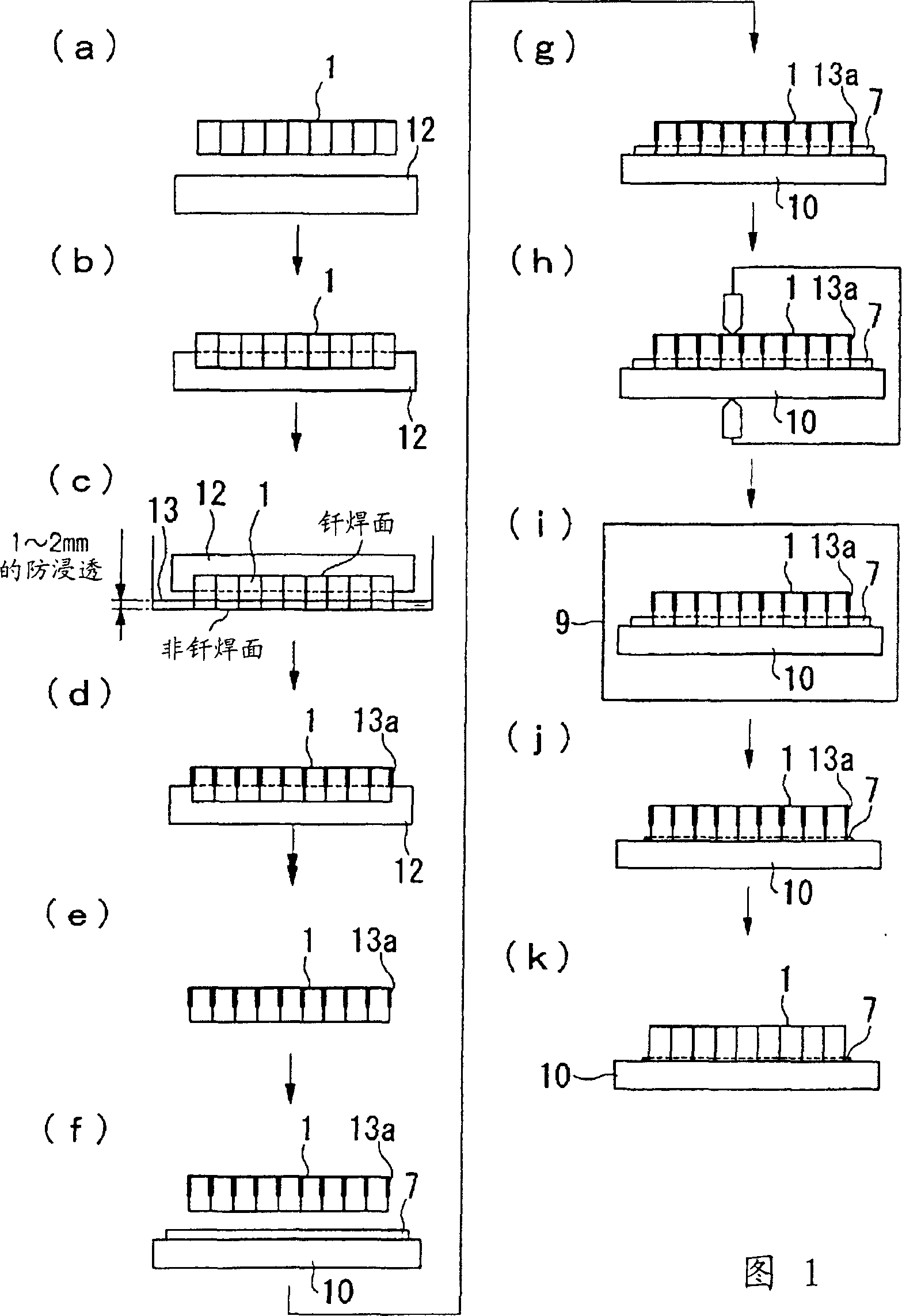
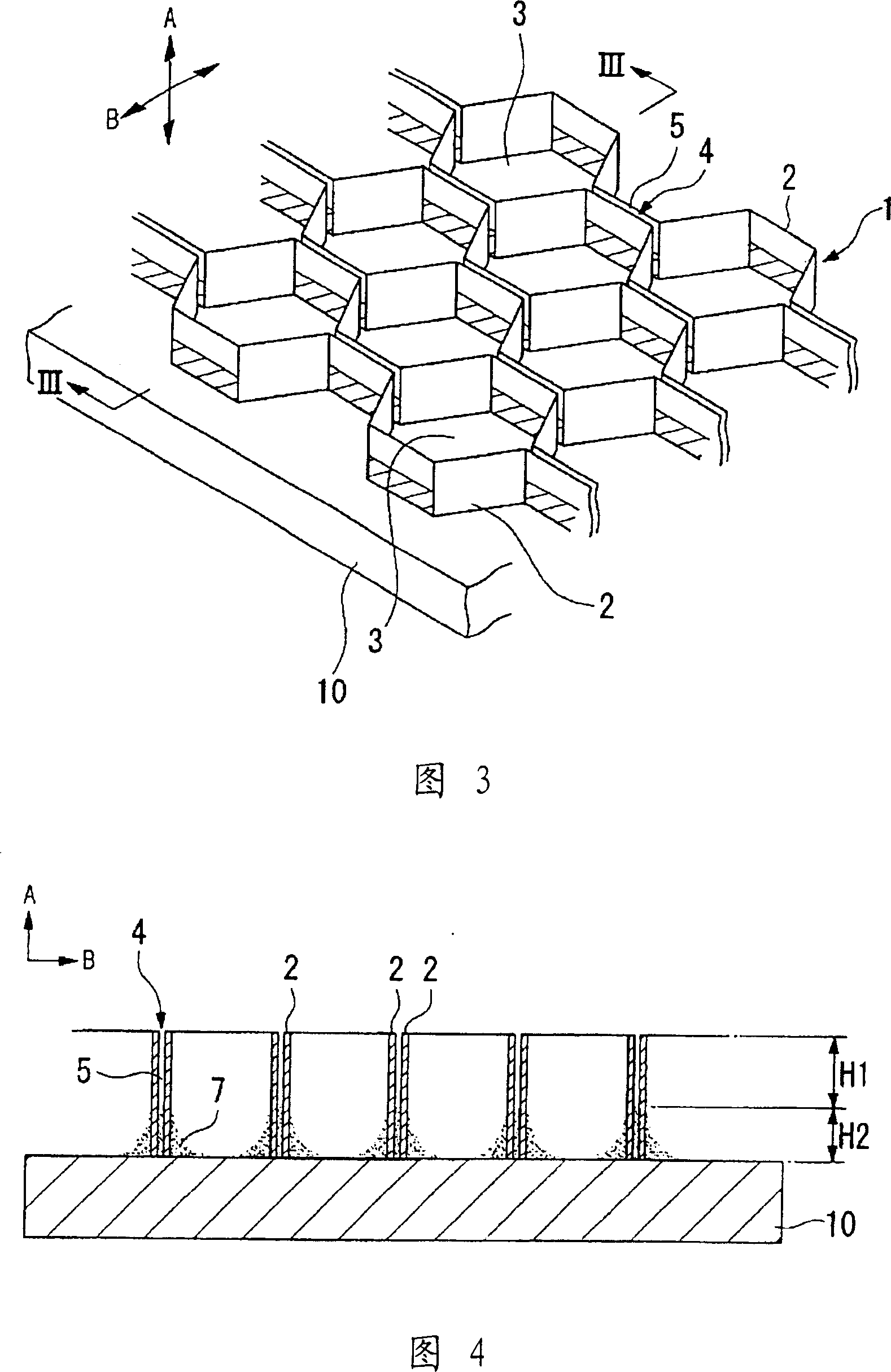
[0032] As shown in FIG. 3 , the honeycomb seal 1 is fixed by brazing to the upper surface (inner peripheral surface) of the base material (separator ring, etc.) 10 on the casing side opposite to the rotary turbine blade (not shown). In order to have machinability in the direction A perpendicular to the plate surface of the base material 10 and sealability in the direction B parallel to the same plate surface, the honeycomb seal 1 has a honeycomb cell region structure composed of voids and partition walls. The plate-like body is formed, and the symbol 3 in the same figure represents a plurality of cells (cell regions) in the shape of a honeycomb (honeycomb).
[0033] The honeycomb seal 1 forms a honeycomb unit 3 by vertically combining a plurality of corrugated thin plates 2 on the plate surface in the vertical direction A, so there is a small gap at the overlapping portion 4...
PUM
 Abstract
Description
Claims
Application Information
 - R&D Engineer
- R&D Manager
- IP Professional
- Industry Leading Data Capabilities
- Powerful AI technology
- Patent DNA Extraction
Browse by: Latest US Patents, China's latest patents, Technical Efficacy Thesaurus, Application Domain, Technology Topic, Popular Technical Reports.
© 2024 PatSnap. All rights reserved.Legal|Privacy policy|Modern Slavery Act Transparency Statement|Sitemap|About US| Contact US: help@patsnap.com