Diffractive and refractive mixed optical element for providing aspherical degree and design method thereof

A technology of diffractive optical elements and optical elements, which is applied in the direction of optical elements, optics, lenses, etc., can solve the problems of multiple structural periods, narrowing range, and small minimum period intervals, etc., and achieves expanded application range, convenient and reliable degrees of freedom, and high Effect of Surface Accuracy

Inactive Publication Date: 2007-03-21
ZHEJIANG UNIV
View PDF4 Cites 0 Cited by
  • Summary
  • Abstract
  • Description
  • Claims
  • Application Information

AI Technical Summary

Problems solved by technology

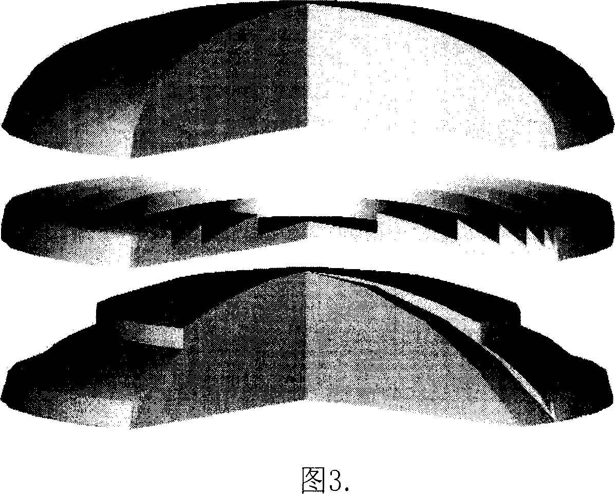
[0006] Traditional binary microstructured diffractive optical elements are usually fabricated on a flat substrate, as shown in Figure 3(b), the binary microstructured surface not only provides phase compensation, but also bears the main optical power of the element, so the structural period More, the corresponding minimum cycle interval becomes smaller, and due to the limitation of the minimum processing line width, the applicable range is greatly reduced

Method used


Image

  • Diffractive and refractive mixed optical element for providing aspherical degree and design method thereof
  • Diffractive and refractive mixed optical element for providing aspherical degree and design method thereof
  • Diffractive and refractive mixed optical element for providing aspherical degree and design method thereof

Examples


Embodiment 1

[0055] Fig. 6 is an example of replacing the laser beam collimating aspheric lens with a diffractive / refractive hybrid optical element composed of a spherical substrate combined with a binary microstructure surface. The structural parameters of this aspheric surface are: curvature c=0.5483, quadric surface coefficient k=0, high-order aspheric surface coefficient α 2 =-0.0114, α 3 =-0.0036, after calculation, when the aspheric surface is replaced by a diffractive / refractive hybrid optical element composed of a spherical base binary microstructure surface, the structural parameters of the optimal spherical base and the binary microstructure diffractive optical element are: the optimal spherical curvature c 0 =0.5051, the surface period of the binary microstructure is 27, and the intervals between three consecutive minimum periods are: 24 μm, 22 μm and 21 μm. Considering that there may be non-periodic rings on the edge or in the middle, the design program lists three consecutiv...

Embodiment 2

[0057] Fig. 7 shows an example of using a diffractive / refractive hybrid optical element composed of a spherical substrate combined with a binary microstructure surface to replace a large aspheric surface in an optical system with an aperture of Φ=90mm. The asphericity of this aspheric surface is relatively large, and it is a high-order aspheric surface, with a curvature c=0.007612, a quadratic surface coefficient k=-5.463953, and a high-order aspheric surface coefficient α 2 = 1.3416435e -7 , α 3 =-4.2867228e -11 . The calculated structural parameters of the optimal spherical substrate and the binary microstructured diffractive optical element are: equivalent spherical curvature c 0 =0.006835, the surface period of the binary microstructure is 483, and the intervals of three consecutive minimum periods are: 22μm, 21μm and 20μm, which are also within the micromachinable range, so as long as the appropriate optimal spherical substrate is selected, most All aspheric surfaces ...


PUM


Abstract

This invention discloses a diffraction-refraction mixed optical element and its design method providing non-sterad. This element is composed of a spherical base and binary microstructure diffraction optical surface, taking a designed wavelength and a smallest processing line width as the criterion to determine spherical base curvature and utilizing the spherical base to bear the main light focal power: processing a binary micro-structure surface diffraction optical element on the spherical base for compensating the optical path difference between spherical base and non-sphere and the smallest periodic interval of the binary microstructure is in the sphere of the smallest processing line-width by the mixed optical method to process the lead-in non-sterad and make the image quality approach the diffraction limit under the condition of realizing total sphere.

Description

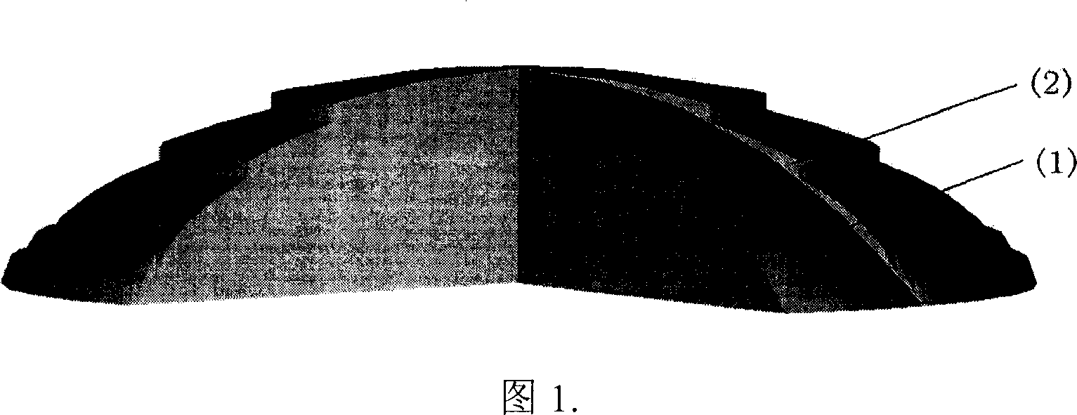
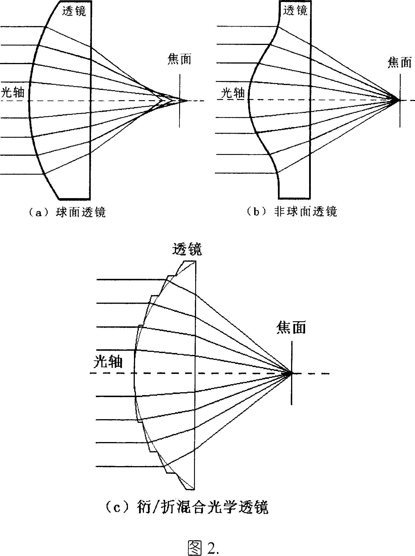
technical field [0001] The invention relates to a diffraction / refraction hybrid optical element providing asphericity and a design method thereof. Background technique [0002] According to the optical path characteristics and imaging characteristics of the spherical system, a single spherical lens can only form a perfect image for a paraxial object point with a thin beam. The light rays parallel to the optical axis incident on a plano-convex lens composed of a spherical surface converge at different positions on the optical axis with the height of the incident point. As shown in Figure 2(a), the imaging defect of this monochromatic light is spherical Difference. Theoretically speaking, a plano-convex lens composed of an aspheric surface instead of a spherical surface can effectively converge all incident rays parallel to the optical axis to one point, as shown in Figure 2(b). The plano-convex lens disclosed by the present invention is composed of a spherical base binary m...

Claims


Application Information

Patent Timeline
Patent Type & Authority Patents(China)
IPC IPC(8): G02B3/00G02B27/42
Inventor 杨国光马韬白剑侯西云
Owner ZHEJIANG UNIV
Why Eureka
Try Eureka