Longitudinal of vacuum circuit breaker transmission

A technology of vacuum circuit breaker and transmission mechanism, applied in the direction of high-voltage air circuit breaker, circuit, electrical components, etc., can solve the problems of reduced mechanism reliability, large contact bounce, large closing power of spring mechanism, etc., and achieve breaking performance. Reliable, small closing bounce, small closing power

Inactive Publication Date: 2007-03-14
SHENYANG HAOCHENG ELECTRICAL SCI & TECH
View PDF3 Cites 0 Cited by
  • Summary
  • Abstract
  • Description
  • Claims
  • Application Information

AI Technical Summary

Problems solved by technology

At present, the longitudinal vacuum circuit breakers that have been used are large in size and the closing work of the spring mechanism is too large, which reduces the reliability of the mechanism. At the same time, the contact bounce is relatively large when closing, and the bounce value of some products has exceeded the required value of the technical standard. , At the same time, the breaking performance is not stable enough, etc.
Due to the large volume of the vacuum circuit breaker, the switchgear is large in size and occupies a large area, which does not meet the needs of modern urban construction

Method used


Image

  • Longitudinal of vacuum circuit breaker transmission
  • Longitudinal of vacuum circuit breaker transmission

Examples


Embodiment 1

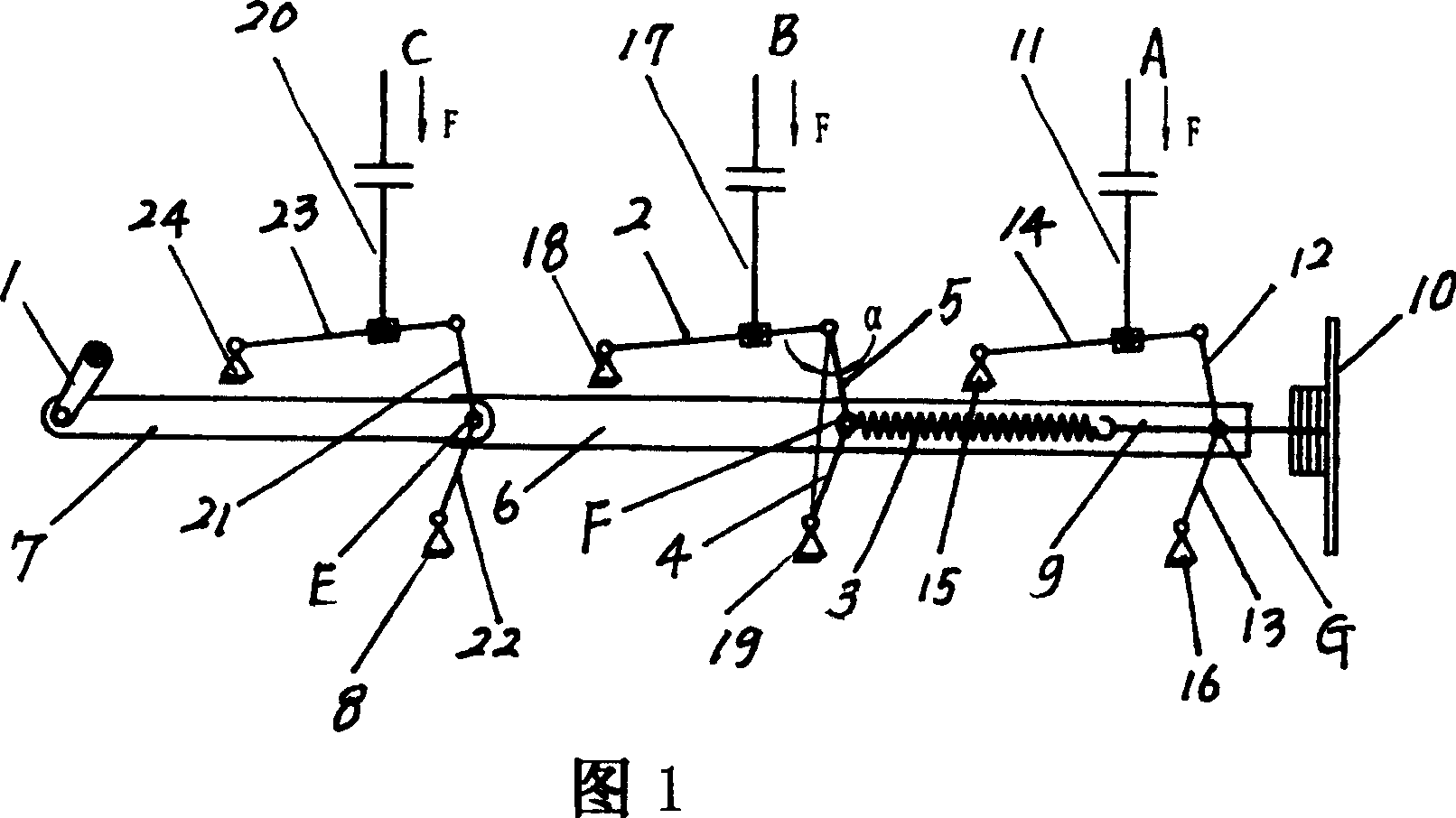
[0020] The transmission mechanism of the longitudinal vacuum circuit breaker includes the front connecting rod 7, the rear connecting rod 6, the opening spring 3, the pull rod mechanism of A phase, the pull rod mechanism of B phase and the pull rod mechanism of C phase.

[0021] The front end of front connecting rod 7 is hinged a mechanism shaft 1, and the rear end of front connecting rod 7 is connected with the front end of rear connecting rod 6 by axis E. A shaft F and a shaft G are respectively fixed at set positions on the rear link 6 .

[0022] The A-phase pull rod mechanism includes a pull rod 11 , an upper link 12 , a lower link 13 and an arc extinguishing chamber crank arm 14 . The lower end of the pull rod 11 is hinged with the arc extinguishing chamber crank arm 14 , one end of the arc extinguishing chamber crank 14 is hinged with the fixed fulcrum 15 , and the other end is hinged with the upper end of the upper link 12 . The lower end of the upper connecting rod 12...

Embodiment 2

[0027] The second embodiment is basically the same as the first embodiment, except that the angle between the connection line between the upper link 12 and the lower link 13 and the upper link 12 after closing is 3°; after closing, the upper link 5 The angle between the line connecting the lower link 4 and the upper link 5 is 3°; the angle between the line connecting the upper link 21 and the lower link 22 and the upper link 21 after closing is 3° .

[0028] The characteristics of closing and opening force are analyzed as follows:

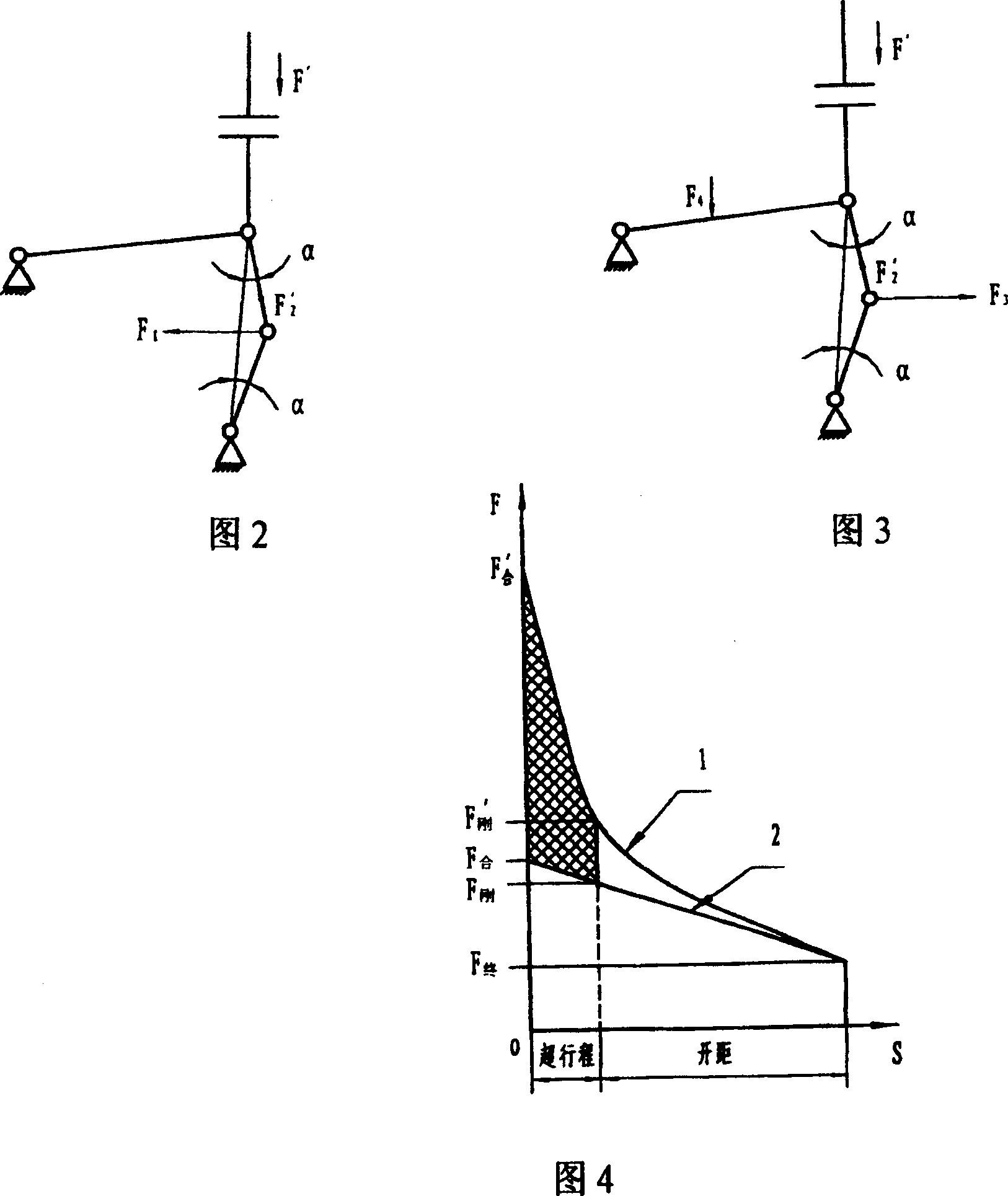
[0029] A. Characteristic analysis of closing force:

[0030] See Figure 2. When connecting rod 4 is equal to connecting rod 5, it can be obtained from calculation:

[0031] F1=2SinαF2'

[0032] After the structure is closed, the α angle is controlled at 3°

[0033] F1=2Sin3°F2'

[0034] =0.1F2'

[0035] When the α angle is controlled at 10°

[0036] F1=2Sin10°F2'

[0037] =0.35F2'

[0038] It can be seen from the relationship that ...


PUM


Abstract

The invention consists of front rod, back link, break brake spring and drag link mechanisms of A phase, B phase, C phase. The front rod makes hinge with back link. The drag link mechanisms of A phase, B phase, C phase have same structure that includes drag link, up connecting rod, low connecting rod and regulating crank of explosion chamber. The lower end of drag link makes hinge with regulating crank of explosion chamber. The one end of regulating crank of explosion chamber makes hinge with fixed pivot, the other end makes hinge with up end of up connecting rod. The lower end of up connecting rod makes hinge with up end of lower connecting rod. The lower end of lower connecting rod makes hinge with fixed pivot. When switch on, the connecting line from the up end of up connecting rod to lower end of lower connecting rod have 3deg-10deg included angle with up connecting rod, the one end of break brake spring is connected with back connecting rod, the other end is connected with spring seat through a connecting rod.

Description

(1) Technical field [0001] The invention relates to a transmission mechanism of a circuit breaker, in particular to a transmission mechanism of a vacuum circuit breaker installed longitudinally with small closing bounce, reliable breaking performance and reduced closing work. (2) Background technology [0002] Vacuum circuit breakers are key equipment in the power transmission and distribution industry. Vacuum circuit breakers are installed in various switchgears. At present, the longitudinal vacuum circuit breakers that have been used are large in size and the closing work of the spring mechanism is too large, which reduces the reliability of the mechanism. At the same time, the contact bounce is relatively large when closing, and the bounce value of some products has exceeded the required value of the technical standard. , At the same time, the breaking performance is not stable enough. Due to the large volume of the vacuum circuit breaker, the switchgear is large in size...

Claims


Application Information

Patent Timeline
Patent Type & Authority Patents(China)
IPC IPC(8): H01H33/42H01H33/66
Inventor 王德元冯文伶关振哲王彬彬
Owner SHENYANG HAOCHENG ELECTRICAL SCI & TECH
Why Eureka
Try Eureka