
Lyophobic film coating part, liquid spraying device and member

A technology of jetting device and liquid jetting head, applied in the direction of coating, electrical components, layered products, etc., can solve the problem that ink is difficult to guide through or reach, achieve excellent lyophobicity, high density, and reduce gear operation failures Effect

Inactive Publication Date: 2007-03-14
SEIKO EPSON CORP
View PDF11 Cites 2 Cited by
  • Summary
  • Abstract
  • Description
  • Claims
  • Application Information

AI Technical Summary

Problems solved by technology

Therefore, there is a possibility that ink may have difficulty being guided through or to these components

Method used


Image

  • Lyophobic film coating part, liquid spraying device and member
  • Lyophobic film coating part, liquid spraying device and member
  • Lyophobic film coating part, liquid spraying device and member

Examples


Embodiment Construction

[0095] Referring to preferred embodiments of the present invention, the lyophobic film coating part, the member of the liquid ejection device, the nozzle plate of the liquid ejection head, the liquid ejection head and the liquid ejection device of the present invention will be described in more detail below.

[0096] A method of forming an undercoat film and a metal alkoxide film described below is an embodiment of the present invention in which a nozzle plate of a liquid ejection head serving as a substrate and formed of stainless steel is to be coated with a lyophobic film. However, the present invention is not limited thereto.

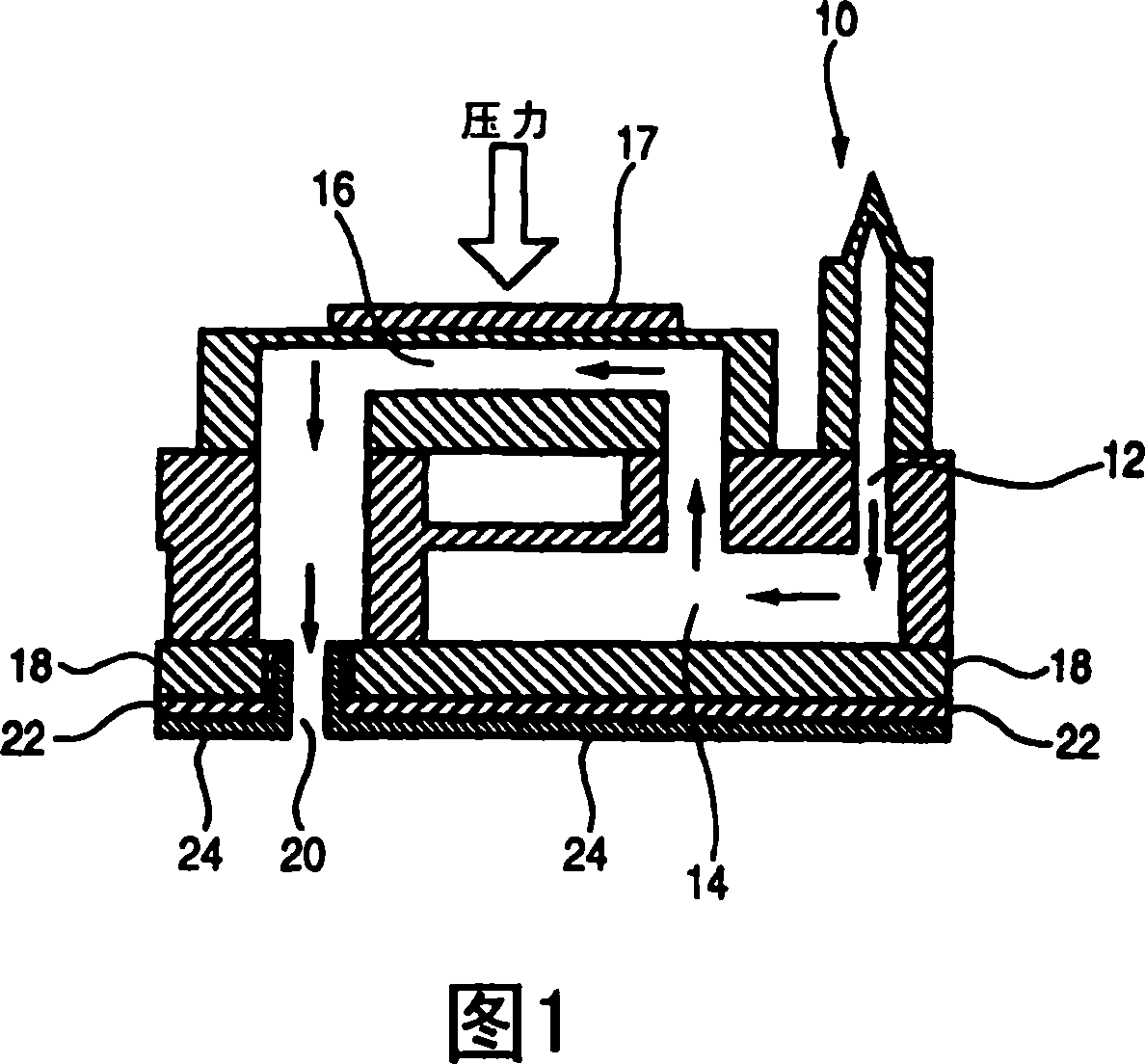
[0097] 1 shows a cross-sectional view of an inkjet printer head 10, which is a liquid ejection head (a part of a liquid ejection device), using ink droplets as liquid droplets to be ejected through nozzle openings. An example. The inkjet printer head 10 has an ink guide groove 12 through which ink is introduced into the inside of the head. The ink...


PUM

PropertyMeasurementUnit
roughnessaaaaaaaaaa
molecular weightaaaaaaaaaa

Abstract

The present invention provides a member comprising a substrate, an undercoat film formed on a surface of the substrate, and a liquid-repellent film of metal alkoxide formed on a surface of the undercoat film. Also disclosed are nozzle head, liquid-jet head and liquid-jet device employing the above-described member.

Description

technical field [0001] The present invention relates to a liquid-repellent film-coated part, a member of a liquid ejection device, a nozzle plate of a liquid ejection head, a liquid ejection head, and a liquid ejection device. More specifically, the present invention relates to a liquid ejecting device having an undercoat film and a lyophobic film formed of a metal alkoxide molecular film, the lyophobic film being formed not only on the liquid ejecting head nozzle of the liquid ejecting device not only on the surface of the board substrate but also on the surfaces of other members of the liquid ejection device (including parts other than metal parts such as resin parts and composite material parts). Background technique [0002] An inkjet printer head (one example of a liquid ejection head) that ejects liquid droplets to a medium through its nozzle openings has a nozzle plate in which a plurality of fine ink ejection ports are formed Ink is ejected from the ink port. If in...

Claims


Application Information

Patent Timeline
Patent Type & Authority Patents(China)
IPC IPC(8): B41J2/05B41J2/16B41J2/135B32B9/00B41J2/14B41J2/165C09D183/00C09D185/00
CPCB41J2/1646B41J2/1606B41J2/1433B41J2002/14419B41J2/1626B41J2/1642B41J2/162H03K3/037H03K3/012
Inventor 宫岛弘夫足助慎太郎松尾泰秀市川祐永小池保则
Owner SEIKO EPSON CORP
Learn More