
An improved motor rotor

An improved technology for motor rotors, applied in the direction of electromechanical devices, electrical components, electric components, etc., can solve the problems of difficult disassembly and reinstallation, affecting the normal operation of the motor, permanent magnet disassembly cannot be disassembled at the same time, and achieves the convenience of later maintenance Effect

Active Publication Date: 2022-05-03
东莞市锦润电机科技有限公司
View PDF5 Cites 0 Cited by
  • Summary
  • Abstract
  • Description
  • Claims
  • Application Information

AI Technical Summary

Problems solved by technology

[0004] 1. The permanent magnets on the rotor yoke are all glued together, and it is difficult to quickly disassemble and reinstall the permanent magnets in the later maintenance. For the permanent magnets, this installation method will only lead to damage to the rotor. The production and maintenance efficiency is reduced, which affects the normal operation of the motor;
[0005] 2. When the permanent magnets on the rotor yoke are installed, each permanent magnet is bonded with glue separately, and the number of permanent magnets on each rotor yoke is not small, and for the maintenance of the later rotor, the permanent magnets It is impossible to disassemble one or more of them at the same time, which is very inconvenient for both the production of the rotor and the later maintenance.

Method used


Image

  • An improved motor rotor
  • An improved motor rotor
  • An improved motor rotor

Examples


Embodiment Construction

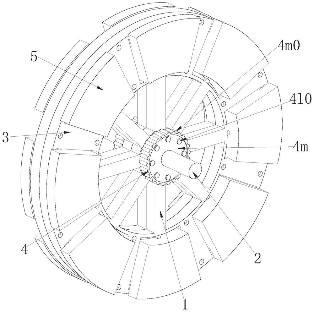
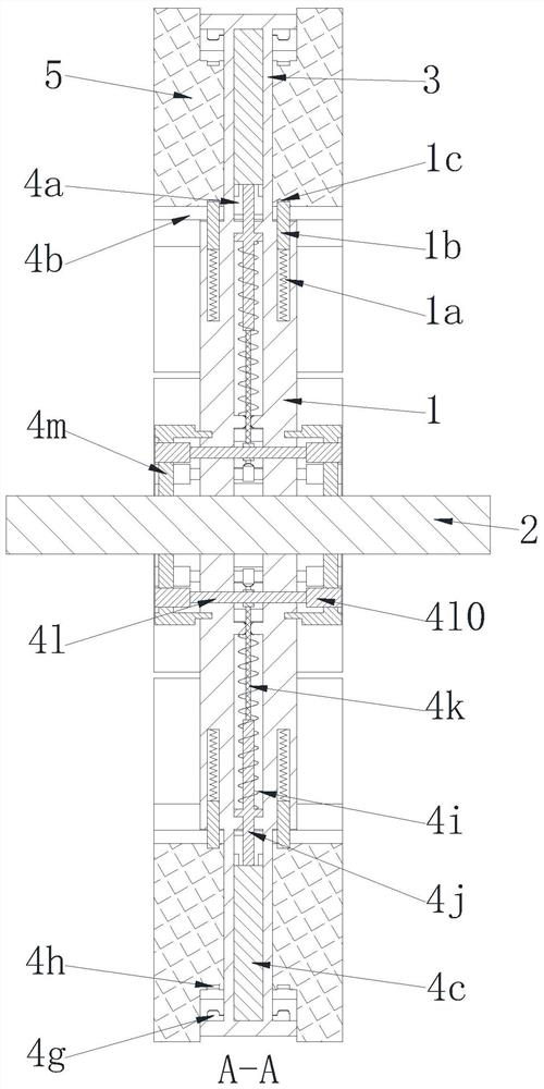
[0029] In order to make the technical means realized by the present invention, creative features, goals and effects easy to understand, the following combination Figure 1 to Figure 6 , to further elaborate the present invention.

[0030] An improved motor rotor, including a rotor bracket 1, a rotating shaft 2, a rotor yoke 3, an installation unit 4 and a permanent magnet 5, two rotor brackets 1 are symmetrically arranged and connected by bolts, and the two A rotating shaft 2 is fixedly installed in the middle of the rotor bracket 1, and a rotor yoke 3 is fixedly installed on the outer edge of the rotor bracket 1. Several installation units 4 are jointly arranged on the rotor bracket 1 and the rotor yoke 3 along the circumferential direction thereof, and each installation unit 4 is symmetrically installed with a permanent magnet 5; wherein:

[0031] The installation unit 4 includes an installation cavity 4a, an installation groove 4b, an installation top block 4c, an installa...


PUM


Abstract

The invention relates to an improved motor rotor, which includes a rotor bracket, a rotating shaft, a rotor yoke, an installation unit and a permanent magnet. Two rotor brackets are symmetrically arranged and connected by bolts, and the middle of the two rotor brackets is A rotating shaft is fixedly arranged, and a rotor yoke is fixedly arranged on the outer edge of the rotor bracket. Several installation units are jointly arranged on the rotor bracket and the rotor yoke along the circumferential direction thereof, and permanent magnets are symmetrically installed on each installation unit. The present invention can solve the following problems in the current design of the motor rotor: the permanent magnets on the rotor yoke are all bonded by glue, and it is difficult to realize rapid disassembly and reinstallation, resulting in a decrease in the production and maintenance efficiency of the rotor; The number of permanent magnets on each rotor yoke is not small, and for the later maintenance of the rotor, one or more permanent magnets cannot be disassembled at the same time.

Description

technical field [0001] The invention relates to the field of motor rotor design, in particular to an improved motor rotor. Background technique [0002] The motor rotor is also the rotating part in the motor. The motor consists of two parts, the rotor and the stator. It is used to realize the conversion device of electrical energy and mechanical energy and mechanical energy and electrical energy. The rotor of the motor is divided into two types: the inner rotor rotation mode and the outer rotor rotation mode; The core body is a rotating body, which can output torque (referring to the motor) or receive energy (referring to the generator). The rotation mode of the outer rotor is to use the outer body of the motor as the rotating body. Different methods facilitate the application in various occasions. The present invention is aimed at the design of the rotor of a disc motor. Generally, the rotor and stator of a motor are fitted inside and outside. In order to make the disc mot...

Claims


Application Information

Patent Timeline
Patent Type & Authority Patents(China)
IPC IPC(8): H02K1/30H02K1/28H02K1/27H02K1/2795
CPCH02K1/30H02K1/28H02K1/27H02K1/2793
Inventor 杨爱岭赵恩洋
Owner 东莞市锦润电机科技有限公司
Learn More