
Yarn strap coiling machine and method thereof

A coiler and sliver technology, which is applied in the directions of transportation and packaging, function indication, and delivery of filamentous materials, etc. It can solve the problem of poor coiling style, problem of gap setting, and no consideration of free length. And other issues

Inactive Publication Date: 2007-02-28
MURATA MASCH LTD
View PDF7 Cites 0 Cited by
  • Summary
  • Abstract
  • Description
  • Claims
  • Application Information

AI Technical Summary

Problems solved by technology

[0005] However, the above-mentioned sliver winder does not take into account the gap between the yarn feed roller and the package periphery, that is, the free length of the yarn between the two, so there is a problem in setting the gap, and there are problems. The problem of poor winding style of the package

Method used


Image

  • Yarn strap coiling machine and method thereof
  • Yarn strap coiling machine and method thereof
  • Yarn strap coiling machine and method thereof

Examples


Embodiment Construction

[0037] Hereinafter, embodiments of the present invention will be described with reference to the drawings.

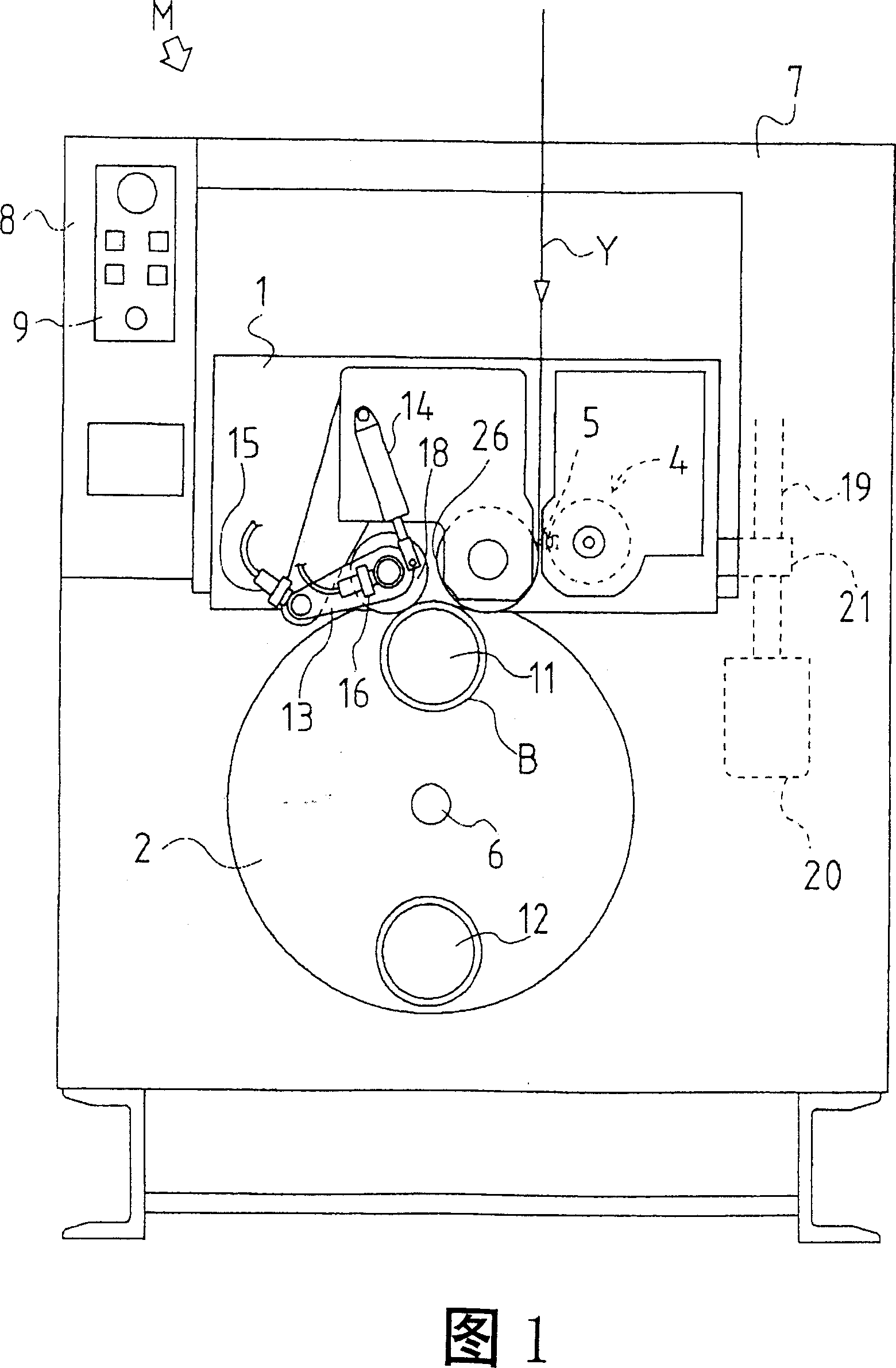
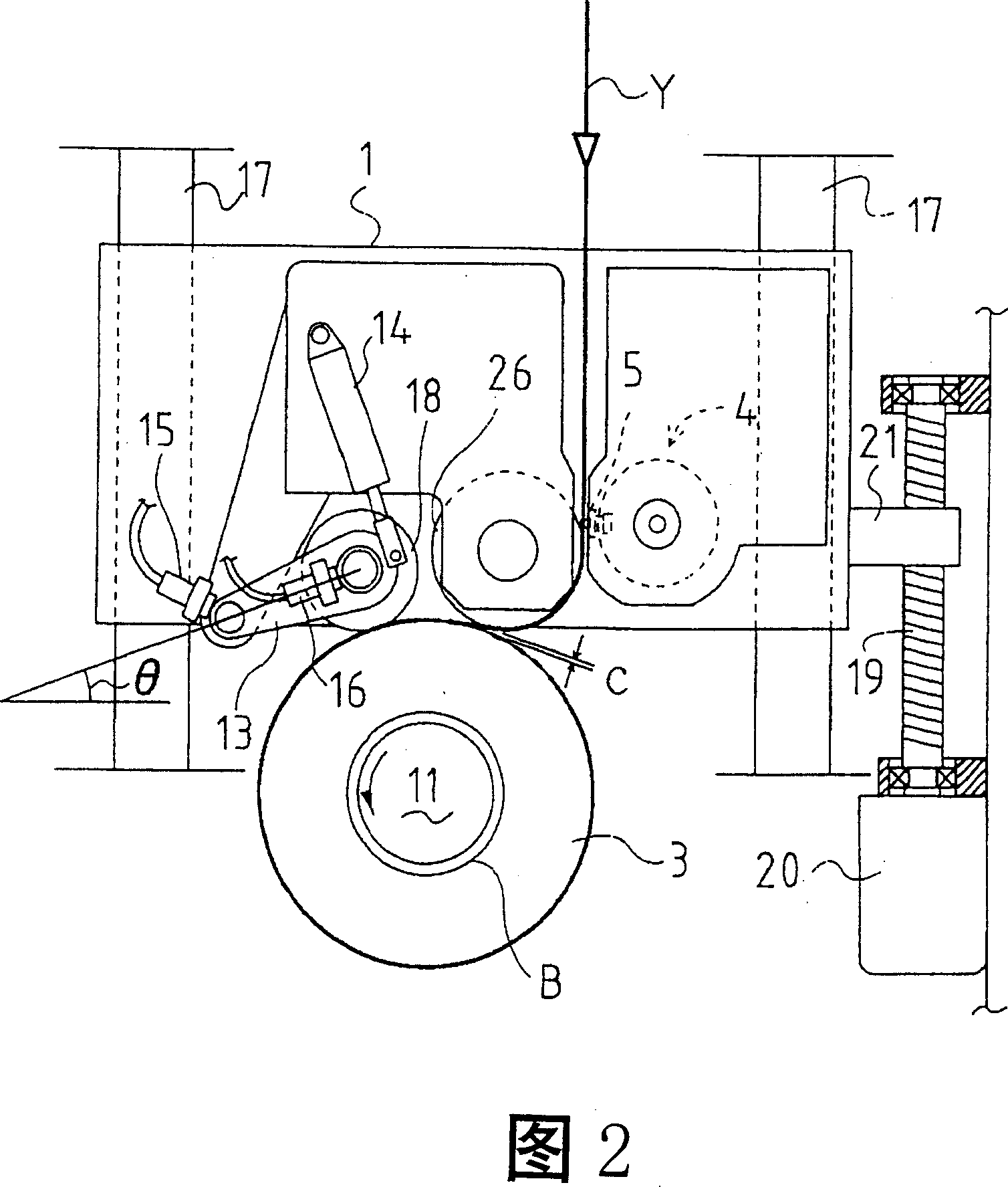
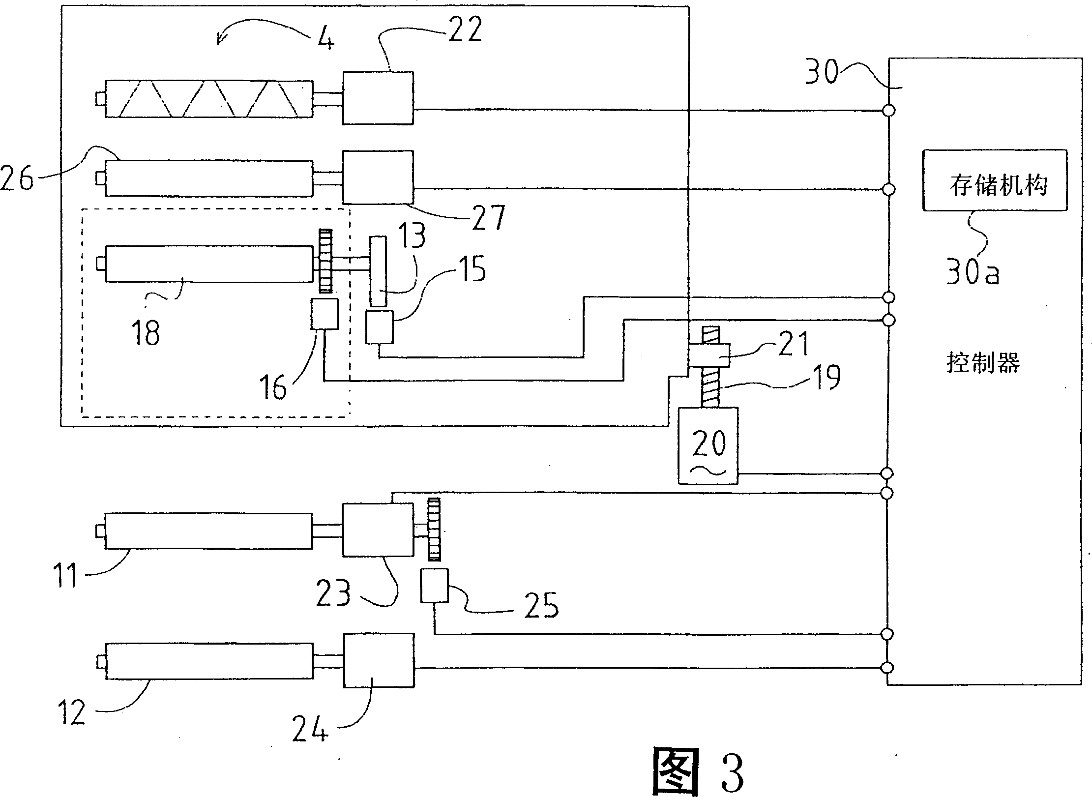
[0038] Fig. 1 is an overall front view of a coiler for elastic yarn. This type of sliver coiler is used for coiling stretchable elastic yarn such as urethane rubber. Fig. 2 is an enlarged front view showing the main structural parts of the slide box. Fig. 3 is a diagram of a control system of a sliver winder. Fig. 4 is a schematic diagram showing the relationship among package diameters, gaps, and contact roller positions. Fig. 5 is a schematic diagram showing the relationship between the gap amount formed between the yarn feed roller and the package, and the free length of the yarn drawn from the feed roller to be wound on the package. Fig. 6 is a schematic diagram showing the relationship between the diameter of the package and the gap when the basic operation is performed with a small gap and the control is performed so that a large gap appears intermittently. Fig...


PUM


Abstract

To solve a problem that a gap between a yarn sending roller and an outer circumference of a package is not considered at all and a wound shape of the package gets poor in a conventional yarn winding machine, the invention relates to a yarn winding machine, which comprises a contact roller (18), a yarn feed roller (26), a roller supporting member (1), and a roller supporting member position adjusting means. The contact roller (18) is supported capable of being displaced relative to the roller supporting member (1) by contacting to the peripheral surface of the package (3), the yarn feed roller (26) which is provided to the upstream side of the contact roller with a space (c) from the peripheral surface of the package, and rotates while contacting the yarn (Y) to the peripheral surface to supply the yarn to the peripheral surface of the package, the roller supporting member (1) for supporting the contact roller and the yarn feed roller, and the roller supporting member position adjusting means for adjusting the position of the roller supporting member in the direction the space (c) changes. And a control means (30) is provided for controlling the roller supporting member position adjusting means so that the space is to be constant irrespective of the package diameter.

Description

technical field [0001] The present invention relates to a sliver winding machine, which is a device for winding yarn onto a bobbin and supplying it as a so-called package. Background technique [0002] Currently known sliver reels are sliver reels with so-called yarn feed rollers. It is equipped with a horizontal reciprocating device and a contact roller, so that the contact roller is crimped on the bobbin, and the yarn is reciprocated laterally by the lateral reciprocating device, and it is continuously supplied to the bobbin. At the same time, the bobbin Rotate to wind the yarn; in this yarn winding machine, a yarn feeding roller is set between the transverse reciprocating device and the contact roller, which can adjust the winding tension of the yarn wound into a package. [0003] The known improved device of this sliver coiler is as described in Japanese Patent Laid-open Report No. 52-37846, and this improved yarn coiler has been developed so that the contact rollers ar...

Claims


Application Information

Patent Timeline
Patent Type & Authority Patents(China)
IPC IPC(8): B65H54/02B65H54/36B65H54/38B65H54/42B65H54/52
CPCB65H54/385B65H2511/14B65H2701/319B65H2511/22B65H54/42B65H54/52B65H54/36B65H2220/01B65H2220/02
Inventor 桥本欣三
Owner MURATA MASCH LTD
Learn More