Method for positioning up branch signal multi-frame and pointer

A pointer positioning and pointer position technology, which is applied in multiplexing communication, time division multiplexing systems, electrical components, etc., can solve the problems of large logic and inappropriate cost performance of FPGA chips, and achieve the effect of reducing logic consumption.

Inactive Publication Date: 2007-02-21
GLOBAL INNOVATION AGGREGATORS LLC
View PDF4 Cites 1 Cited by
  • Summary
  • Abstract
  • Description
  • Claims
  • Application Information

AI Technical Summary

Problems solved by technology

However, such a long delay consumes too much logic in a fast programmable logic array (FPGA), which is not suitable for the cost performance of the current FPGA chip.

Method used


Image

  • Method for positioning up branch signal multi-frame and pointer
  • Method for positioning up branch signal multi-frame and pointer
  • Method for positioning up branch signal multi-frame and pointer

Examples


Embodiment Construction

[0028] The present invention will be further described in detail below in conjunction with the accompanying drawings and specific embodiments.

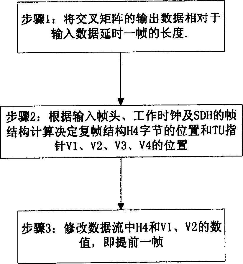
[0029] Such as figure 1 Shown, method of the present invention comprises the following steps at least:

[0030] Step 1: Delay the output data of the cross matrix relative to the input data by one frame length;

[0031] Step 2: Calculate and determine the position of the H4 byte of the multiframe structure and the positions of the TU pointers V1, V2, V3, and V4 according to the frame structure calculation of the input frame header, working clock and SDH;

[0032] Step 3: Modify the values ​​of H4, V1, and V2 in the data stream, that is, one frame ahead, including: modifying the multiframe, modifying the position and value of the TU pointer.

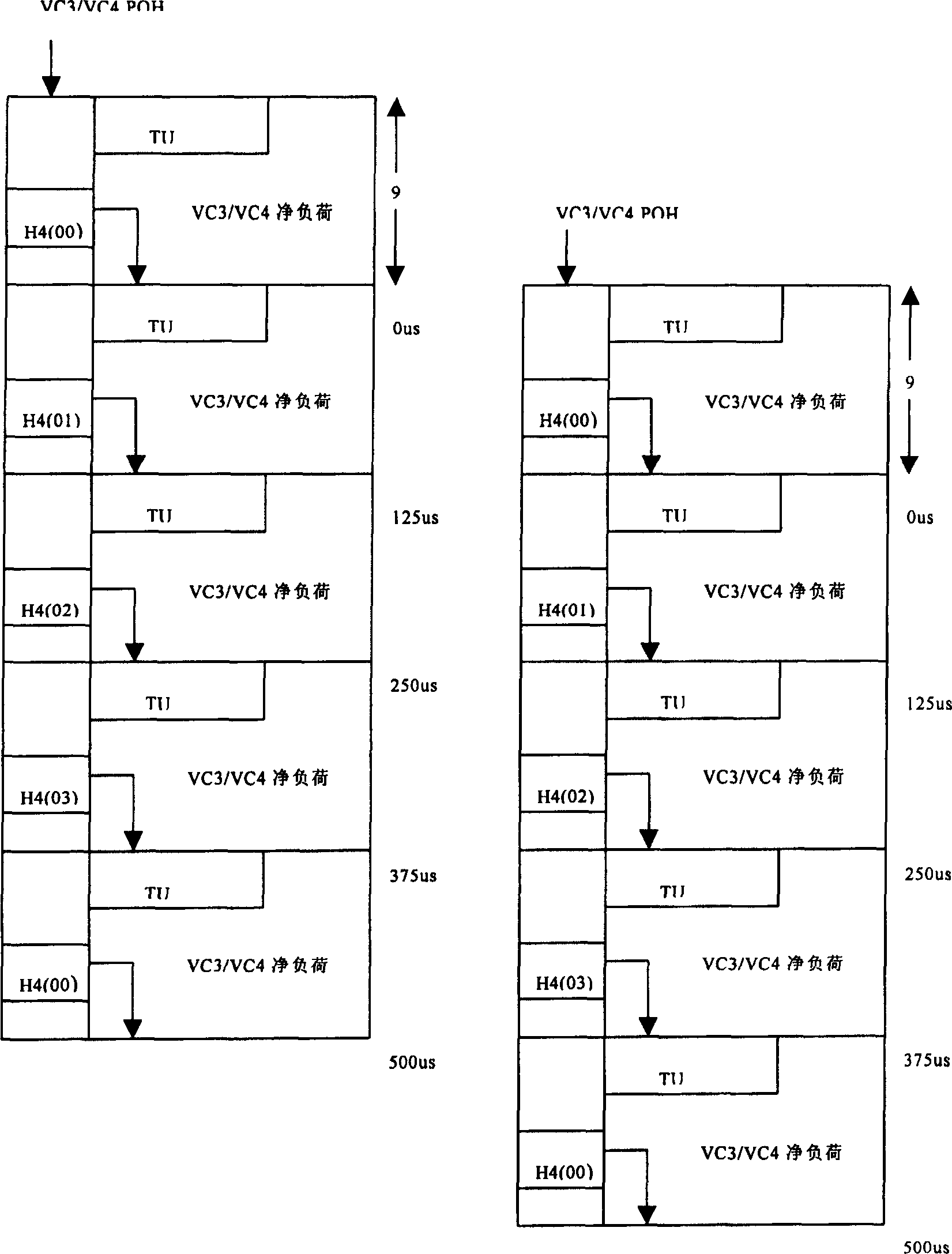
[0033] Such as figure 2 As shown, the signal multiframe and TU pointer after one frame delay are one frame behind the signal before the delay. Therefore, in order to have the same multiframe ...


PUM


Abstract

A upper branch line signal multiframe and pointer positioning method comprising, delaying the output data of the cross-interaction matrix in relative to the input data for the length of one frame, determining the position of H4 byte of the multiframe structure and the position of TU pointer V1, V2, V3 and V4 according to the input frame heading, operation clock and SDH frame structure, modifying the value of H4, V1 and V2 in the data stream which includes, modifying the multiframe, modifying the position of the TU pointer and its value, modifying the corresponding data or information in the data stream to make the multiframe of the input signal in the time slot cross-interaction matrix consistent to the AU pointer.

Description

Technical field: [0001] The invention relates to an optical synchronous digital transmission system in the field of communication, in particular to multiframes of signals in optical synchronous digital transmission equipment and positioning of tributary unit group (Tributary Unit Group, TU for short) pointers. Background technique: [0002] In optical synchronous transmission equipment, the cross-modulation part of the signal is very important, and the level of the signal coordination capability is mainly determined by the size of the cross-connect matrix. Wherein, if the device involves the up and down of Plesiochronous Digital Hierarchy (PDH for short) signals, the cross section of the signals must include a full crossover time-division crossover matrix. [0003] In the design of the full-crossing time-division cross-connect matrix, each group of signals entering the time-division cross-connect matrix must meet the following two conditions: [0004] (a) The signals enteri...

Claims


Application Information

Patent Timeline
Patent Type & Authority Patents(China)
IPC IPC(8): H04B10/12H04B10/08H04Q3/52H04J3/16
Inventor 于莉
Owner GLOBAL INNOVATION AGGREGATORS LLC
Why Eureka
Try Eureka