Method for producing low water peak fiber
A manufacturing method, low water peak technology, applied in the direction of manufacturing tools, glass manufacturing equipment, glass fiber products, etc., can solve problems such as difficulties
- Summary
- Abstract
- Description
- Claims
- Application Information
AI Technical Summary
Problems solved by technology
Method used
Image
Examples
Embodiment 1
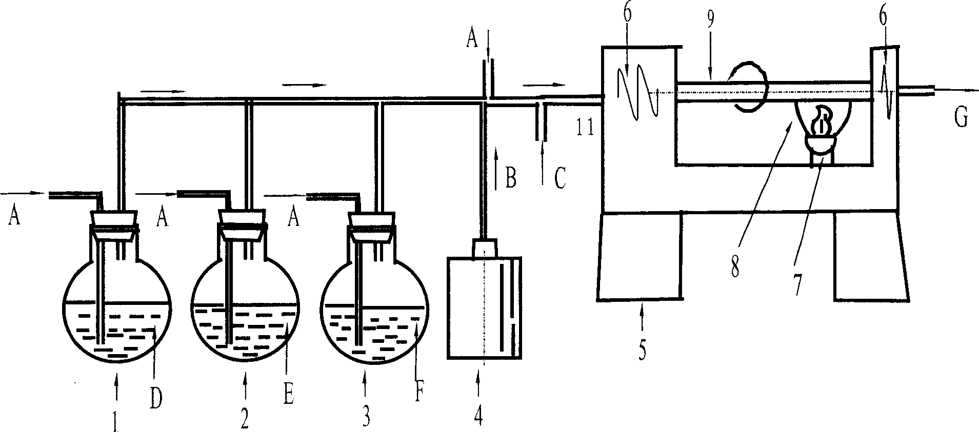
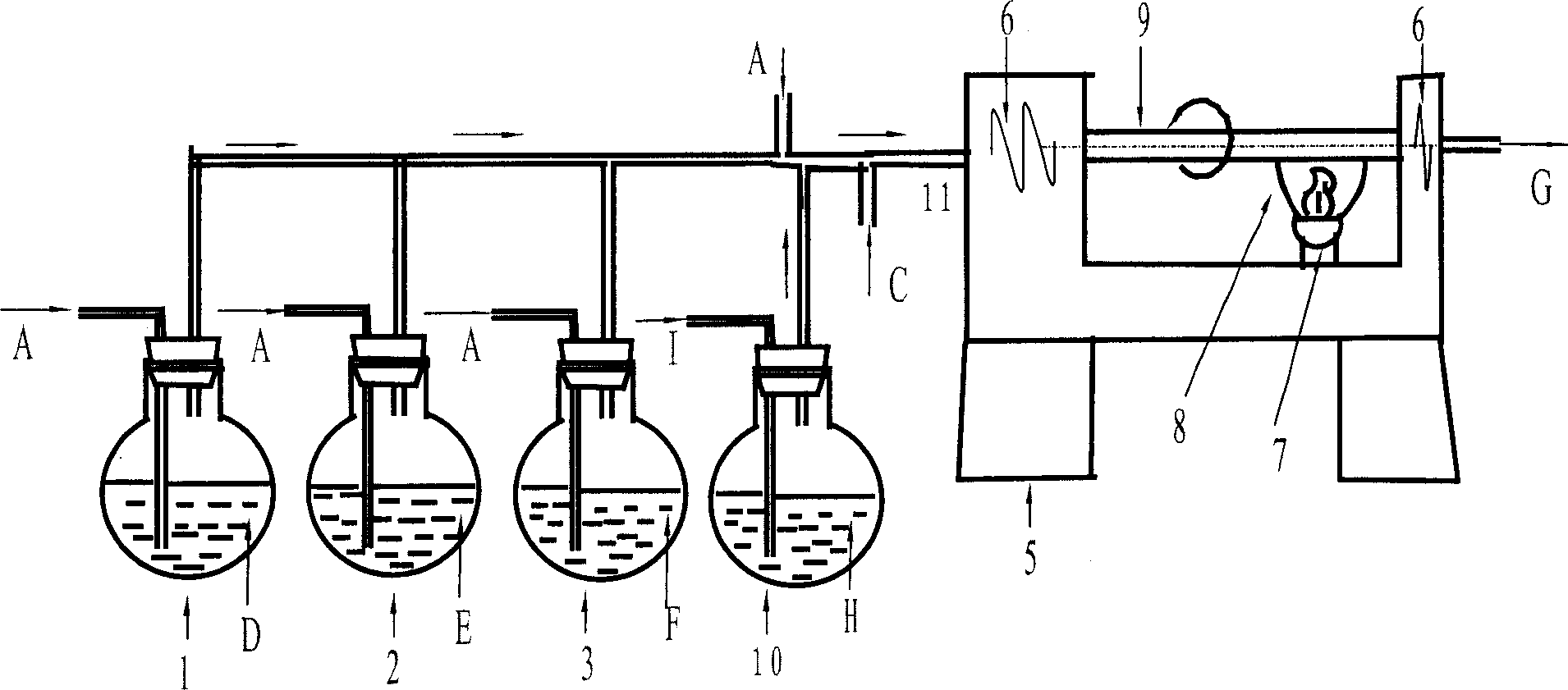
[0087] In a production workshop with a temperature of 25°C, a relative humidity of 5% provided by dry air, and a cleanliness level of 1000 (that is, the cleanliness level M4.5 set by the US Federal Standard), the high-purity raw material Freon / SF 6 , The high-purity oxygen mixed gas is introduced into the quartz substrate tube with a hydroxyl content of 10ppb placed on the MCVD deposition lathe through a sealed pipeline, and the inner wall of the quartz substrate tube is corroded and dehydroxylated at a temperature of 1800°C to reduce the inner surface of the quartz substrate tube. The hydroxyl content of the wall. Then, pass high-purity SiCl 4 , POCl 3 , high-purity oxygen, chlorine, and helium mixed gas, the mixed gas reacts at a temperature of 1350 ° C and deposits a certain thickness of loose-structured powder (Soot) on the inner wall of the quartz substrate tube. Subsequently, at a temperature of 1180° C., after purging with high-purity helium, 4% deuterium (4% D 2 +96...
Embodiment 2
[0094] In a production workshop with a temperature of 25°C, a relative humidity of 10% provided by dry air, and a cleanliness level of 1000 (that is, the cleanliness level M4.5 set by the US Federal Standard), the high-purity raw material Freon / SF 6 The mixed gas of high-purity oxygen is introduced into the quartz substrate tube with a hydroxyl content of 10ppb placed on the MCVD deposition lathe through a sealed pipeline, and the inner wall of the quartz substrate tube is corroded and dehydroxylated at a temperature of 1800 ° C to reduce the quartz substrate. Hydroxyl content of the inner wall of the tube. Then, introduce high-purity SiCl 4 , POCl 3 , high-purity oxygen, chlorine, and helium mixed gas, the mixed gas reacts at a temperature of 1380 ° C and deposits a certain thickness of loose-structured powder (Soot) on the inner wall of the quartz substrate tube. After the high-purity helium is purged, at a temperature of 1200 ° C, heavy water (D 2 O) mixed gas, the Soot ...
Embodiment 3
[0101] In a production workshop with a temperature of 25°C, a relative humidity of 15% provided by dry air, and a cleanliness level of 1000 (that is, the cleanliness level M4.5 set by the US Federal Standard), the high-purity raw material Freon / SF 6 The mixed gas of high-purity oxygen is introduced into the quartz substrate tube with a hydroxyl content of 10ppb placed on the MCVD deposition lathe through a sealed pipeline, and the inner wall of the quartz substrate tube is corroded and dehydroxylated at a temperature of 1800 ° C to reduce the quartz substrate. Hydroxyl content of the inner wall of the tube. Subsequently, at a temperature of 1200°C, after purging with high-purity helium, 2% deuterium (2% D 2 +98% He) mixed gas dehydrates and deuterium-hydrogen exchange the Soot deposited on the inner wall of the quartz substrate tube, and the treatment time is 30 minutes. Soot, which has been fully dehydrated and deuterium-hydrogen exchanged, is vitrified at a temperature of 1...
PUM
| Property | Measurement | Unit |
|---|---|---|
| thickness | aaaaa | aaaaa |
Abstract
Description
Claims
Application Information
 - R&D Engineer
- R&D Manager
- IP Professional
- Industry Leading Data Capabilities
- Powerful AI technology
- Patent DNA Extraction
Browse by: Latest US Patents, China's latest patents, Technical Efficacy Thesaurus, Application Domain, Technology Topic, Popular Technical Reports.
© 2024 PatSnap. All rights reserved.Legal|Privacy policy|Modern Slavery Act Transparency Statement|Sitemap|About US| Contact US: help@patsnap.com


