Integrated manual multiple directional control valve for lader

A multi-way reversing valve, integrated technology, applied in the direction of lifting device, mechanical equipment, fluid pressure actuating device, etc., can solve the problems of environmental pollution, easy oil leakage, excessive operating force, etc.

Inactive Publication Date: 2007-01-17
尚继良
View PDF7 Cites 1 Cited by
  • Summary
  • Abstract
  • Description
  • Claims
  • Application Information

AI Technical Summary

Problems solved by technology

However, for the reversing valve with this structure, due to the split structure between the main valve body and the overload valve body, under high temperature and high pressure, the sealing ring between the main valve body and the overload valve body is easy to age and deform. The joint surface between the valve bodies is prone to oil leakage, causing environmental pollution and wasting resources; because the valve stem is a hollow structure and the check valve is built in, the diameter of the valve stem is large, and the circumference line matching the valve body hole is long. The leakage is relatively high, and because the hollow valve stem is difficult to process and the quality is difficult to guarantee, the valve stem is prone to "clamping" and excessive operating force; due to the leakage characteristics of the "slide valve" structure itself, the boom valve stem will The phenomenon of "sinking" occurs, and the sinking speed is too high, which will increase energy consumption and cause serious safety accidents
The authorized announcement number is CN 2355158Y, and the authorized announcement date is a utility model patent on December 22, 1999. It discloses an integral multi-way hydraulic reversing valve, which is equipped with multiple sets of valve stems in the valve body, and unloads the oil chamber. The zigzag unloading oil passage T3 composed of T3′a, T3′b and the unloading oil passage hole T3′ is arranged at the lower end of the valve body. The chamber of the reversing valve with this structure is simple to process, but there is still a large amount of internal leakage. High, boom stem "sinking" phenomenon

Method used


Image

  • Integrated manual multiple directional control valve for lader
  • Integrated manual multiple directional control valve for lader
  • Integrated manual multiple directional control valve for lader

Examples


Embodiment Construction

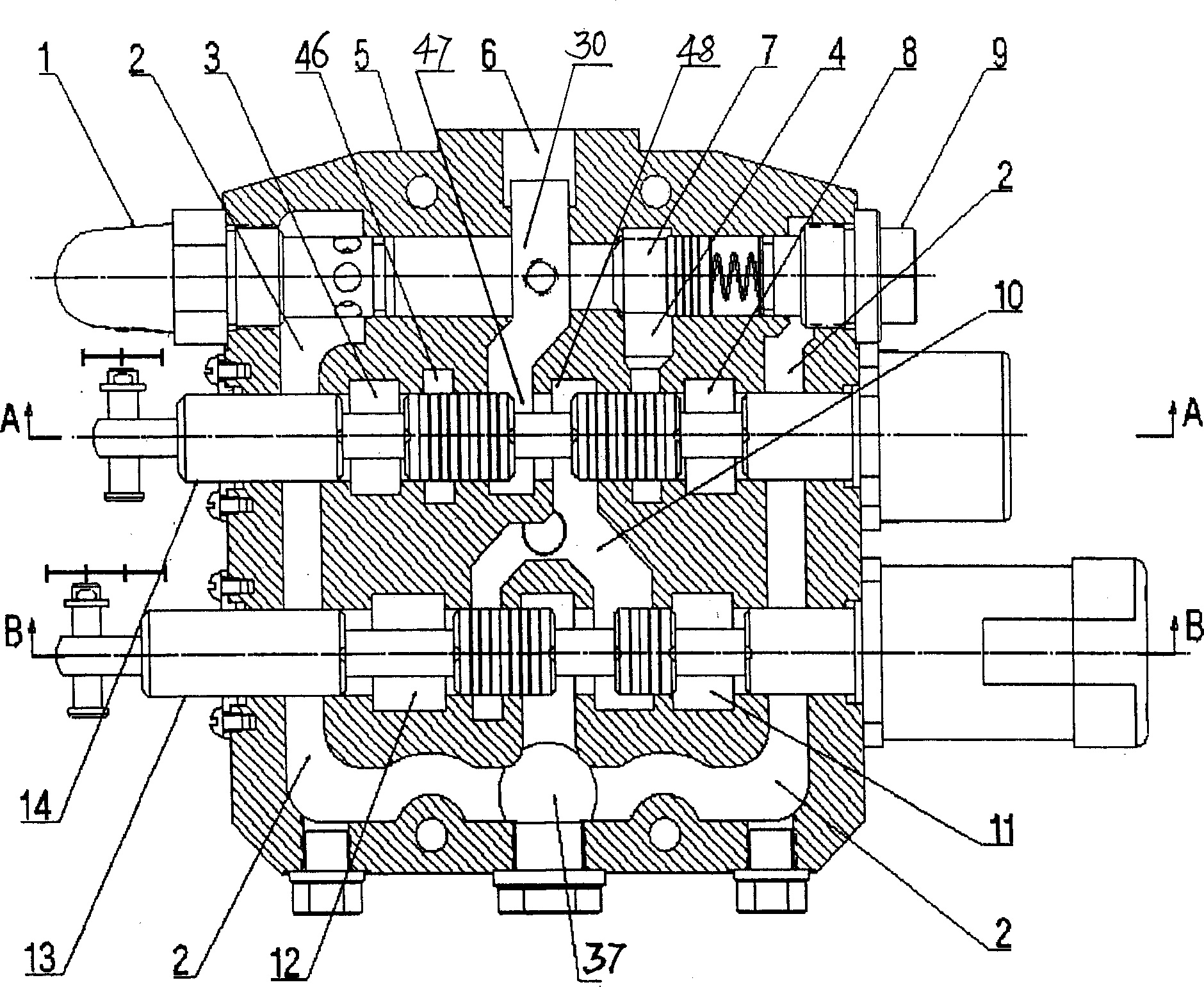
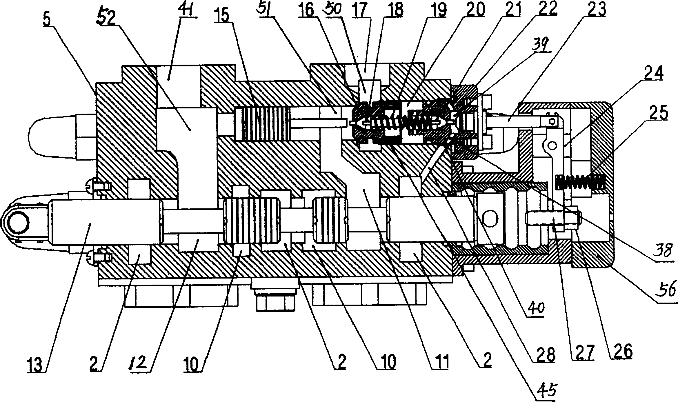
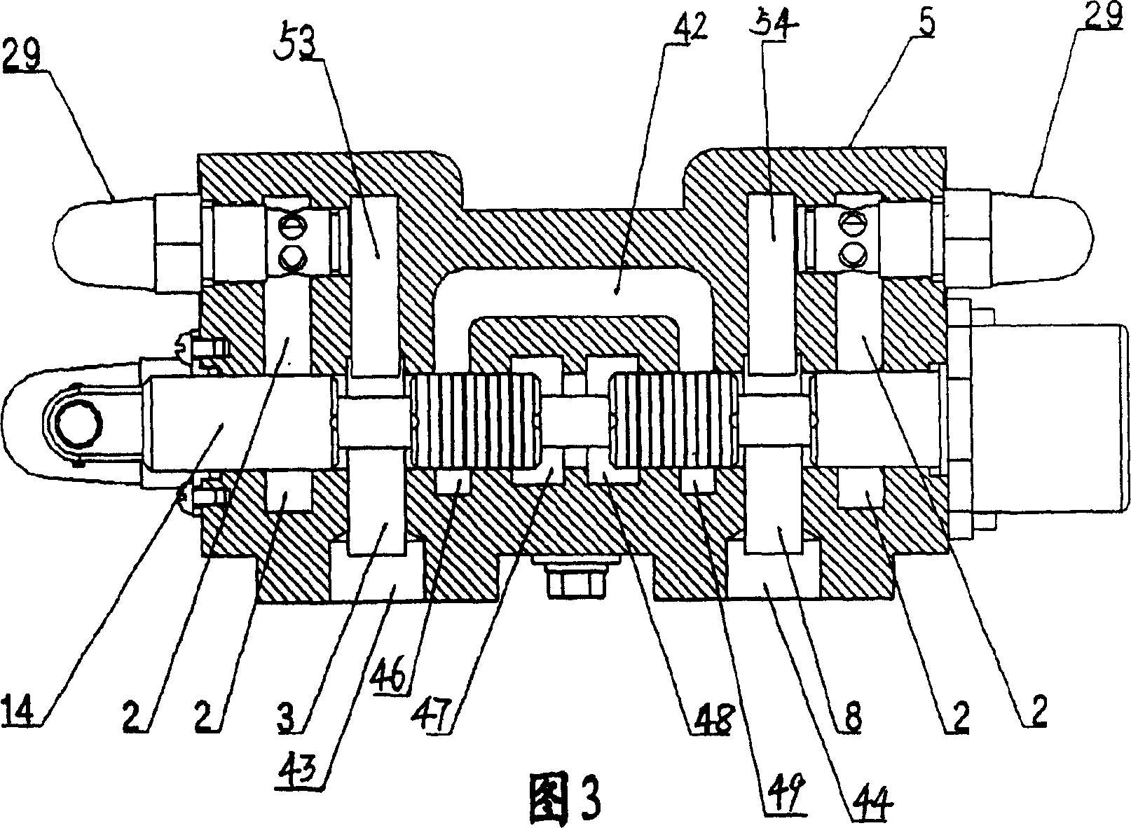
[0020]The integrated manual multi-way reversing valve for the loader shown in the accompanying drawing has three through holes, the first hole 31, the second hole 32, and the third hole 33, along the bottom of the valve body 5. The both sides of valve body above the hole 32 have the 5th hole 35, the 6th hole 36 respectively, have the 4th hole 34 on the top parallel to the 3rd hole 33, the same side of the 6th hole 36, near the first There is a high-pressure oil inlet 6 on the longitudinal side of the hole 31, and an oil return port 37 is arranged on the opposite side of the high-pressure oil inlet 6 and the lower bottom surface of the valve body 5. There are unloading bucket oil ports 43 and bucket receiving oil ports 44 on the bottom surface, and boom lowering oil ports 41 and boom lifting oil ports 17 are opened on the upper bottom surface of the valve body 5 perpendicular to the fourth hole 34; The first hole 31 in the body 5 is provided with four slots from left to right, ...


PUM


Abstract

The invention discloses a integral manual multi-path reversal valve applied in loader, which includes integral valve, six apertures are drilled in the valve, three of them are connected with oil inputting channel and the return channel, the valve has a inlet and a return outlet connected to the channels, the aperture is assembled with a moving arm valve pole, rotary valve pole, safe valve, overload valve, outlay common single-way valve and hydraulic control lock device, the moving arm valve pole and the rotary valve pole are the solid valve pole, the hydraulic control lock has pilot and double-direction starting functions, it is sealed in the oil path with the circle line. The valve hydraulic oil has no leakage, the inner leakage is small, it can prevent the moving arm form falling, avoids the lock and oversize manipulating force, it is safe and flexible.

Description

technical field [0001] The invention relates to an integral manual multi-way reversing valve for a loader. Background technique [0002] The existing integrated manual multi-way reversing valve for loaders is equipped with two overload valve bodies on the main valve body, and an oil inlet circuit and an oil return circuit are arranged between each overload valve body and the main valve body. , the overload valve body is installed with an overload valve, the main valve body is equipped with a hole for installing the bucket valve stem and the boom valve stem, the bucket valve stem and the boom valve stem are all hollow structures, and different oil grooves are provided on each hole The oil tanks are connected by the high-pressure oil inlet and the low-pressure oil return. By moving the bucket valve stem and the boom valve stem in different positions in the hole, the oil tank is connected with the high-pressure oil inlet and the low-pressure oil return. To achieve different re...

Claims


Application Information

Patent Timeline
Patent Type & Authority Patents(China)
IPC IPC(8): F15B13/02B66F9/06
Inventor 尚继良
Owner 尚继良
Why Eureka
Try Eureka