
Integrated fuel pack for fuel cell electric generating system, converter and gas purifier

A fuel cell and power generation system technology, applied in the direction of fuel cell integration, fuel cell components, fuel cells, etc., can solve the problems of reduced power generation efficiency, low hydrogen concentration, and the power generation system cannot obtain power concentration.

Inactive Publication Date: 2006-11-29
CASIO COMPUTER CO LTD
View PDF0 Cites 0 Cited by
  • Summary
  • Abstract
  • Description
  • Claims
  • Application Information

AI Technical Summary

Problems solved by technology

There is also a problem that the power generation efficiency decreases because the concentration of hydrogen gas that contributes to power generation is low in the case where a mixed gas of hydrogen gas and carbon dioxide gas is simply supplied to the fuel cell
In addition, there is the problem that deadly carbon monoxide may also be slightly contained in the mixture
[0011] Furthermore, due to the size of the vapor fuel converter itself, power generation systems known in the prior art cannot achieve sufficient power density for use in portable or portable power systems

Method used


Image

  • Integrated fuel pack for fuel cell electric generating system, converter and gas purifier
  • Integrated fuel pack for fuel cell electric generating system, converter and gas purifier
  • Integrated fuel pack for fuel cell electric generating system, converter and gas purifier

Examples


no. 1 example

[0127] (A) power generation module 10

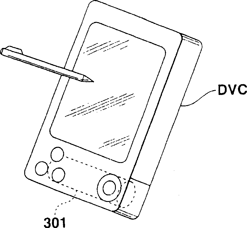
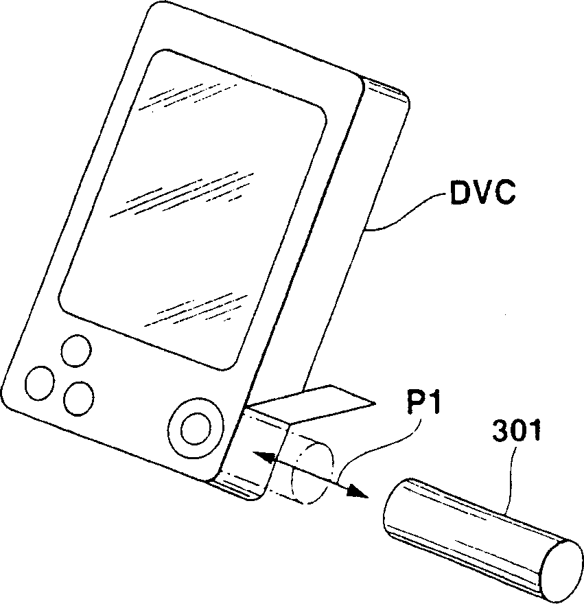
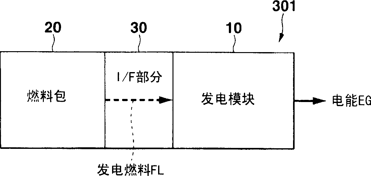
[0128] image 3 is a block diagram showing a first embodiment of a power generating module applied to a power supply system according to the present invention, Figure 4 is a schematic diagram showing the structure of the power supply system according to this embodiment.

[0129] Such as image 3 As shown, the power generation module 10A according to this embodiment continuously and spontaneously generates predetermined power (second power) using the power generation fuel supplied from the fuel pack 20A via the I / F portion 30A, and uses this power as the driving power of the controller CNT (controller power) output and control to drive a load LD (a component or module with multiple functions of the device DVC), the controller CNT is included in at least the device DVC connected to the power supply system 301 . There is also provided a sub power supply section (second power supply means) 11 for outputting electric power as operating p...

no. 2 example

[0352] A second embodiment of a power generating module suitable for use in a power supply system according to the present invention will now be described with reference to the accompanying drawings.

[0353] Figure 32 is a block diagram representing a second embodiment of a power generating module suitable for use in a power supply system according to the invention, Figure 33 is a schematic diagram showing the electrical connection relationship between the power supply system (power generation module) and the device according to this embodiment. Here, like reference numerals denote structures similar to those of the first embodiment described above, thereby simplifying or omitting their explanations.

[0354] Such as Figure 32 As shown, the power generation module 10B according to this embodiment generally includes: a sub power supply part (second power supply device) 11 having a function similar to that of the above-mentioned first embodiment (see image 3 ); power gen...


PUM


Abstract

A by-product elimination device used in a power generation system includes a fuel pack provided with a fuel charged portion having a power generation fluid fuel containing hydrogen, and a power generation module which detachably attached to the fuel pack, the module including a reforming portion which transforms the power generation fuel supplied from the charged portion into first gas containing hydrogen gas and carbon dioxide, and a fuel cell which generates an electrical energy by using the hydrogen gas. The device includes an absorbent charged portion which selectively absorbs carbon dioxide contained in the first gas and feeds second gas whose carbon dioxide concentration is lowered by the first gas to the fuel cell.

Description

technical field [0001] The present invention relates to a device for eliminating by-products in a power supply system, and more particularly to a device for eliminating by-products in a portable power supply system with high energy utilization efficiency. Background technique [0002] Various battery chemistries are used in domestic and industrial fields. For example, primary batteries such as alkaline dry batteries or manganese dry batteries are often used in watches, cameras, toys and portable acoustic devices, and have such a feature that their production volume is large from a global point of view, and they are cheap and readily available. [0003] Accumulators such as lead accumulators, nickel-cadmium accumulators, nickel-metal hydride accumulators, lithium-ion batteries are often used in mobile phones or personal digital assistants (PDAs), which are widely used in recent portable devices such as digital In video cameras or digital still cameras, this battery is charac...

Claims


Application Information

Patent Timeline
Patent Type & Authority Patents(China)
IPC IPC(8): H01M8/06B01J8/02C01B3/32H01M8/00H01M8/02H01M8/04H01M14/00
CPCH01M8/0612Y02E60/50C01B2203/066H01M8/04559H01M2250/30H01M8/0668C01B2203/047C01B2203/84H01M8/04089H01M16/003H01M8/04679Y02B90/12C01B2203/044H01M8/04753H01M8/04223C01B3/323H01M8/04373H01M2250/402C01B2203/0283H01M8/04626H01M8/04171H01M8/04686H01M8/04567C01B2203/0475C01B2203/0233H01M8/04208C01B2203/16H01M8/04425H01M8/04776Y02B90/18C01B2203/042H01M8/04007Y02B90/10H01M8/04303H01M8/04302H01M8/04228H01M8/04225H01M8/06H01M8/0263
Inventor 盐谷雅治
Owner CASIO COMPUTER CO LTD
Learn More