High-temperature burning joint production system for exhaused air from isolation room

A high-temperature combustion and scheduling system technology, applied in the direction of combustion method, combustion type, joint combustion mitigation, etc., can solve the problems of virus diffusion and transmission, and achieve the effects of reducing overall cost, simple structure, and simplified ventilation design

Inactive Publication Date: 2006-08-09
吴晓海
View PDF0 Cites 0 Cited by
  • Summary
  • Abstract
  • Description
  • Claims
  • Application Information

AI Technical Summary

Problems solved by technology

After this kind of residual poison enters the surrounding environment, although the green plants around the site of this kind of room can play a certain role in buffering and diluting it, the residual poison may still continue to have unknown potential effects on humans living in the biosphere through a certain transmission chain. Harm, so that the virus spreads, spreads

Method used


Image

  • High-temperature burning joint production system for exhaused air from isolation room

Examples


Embodiment Construction

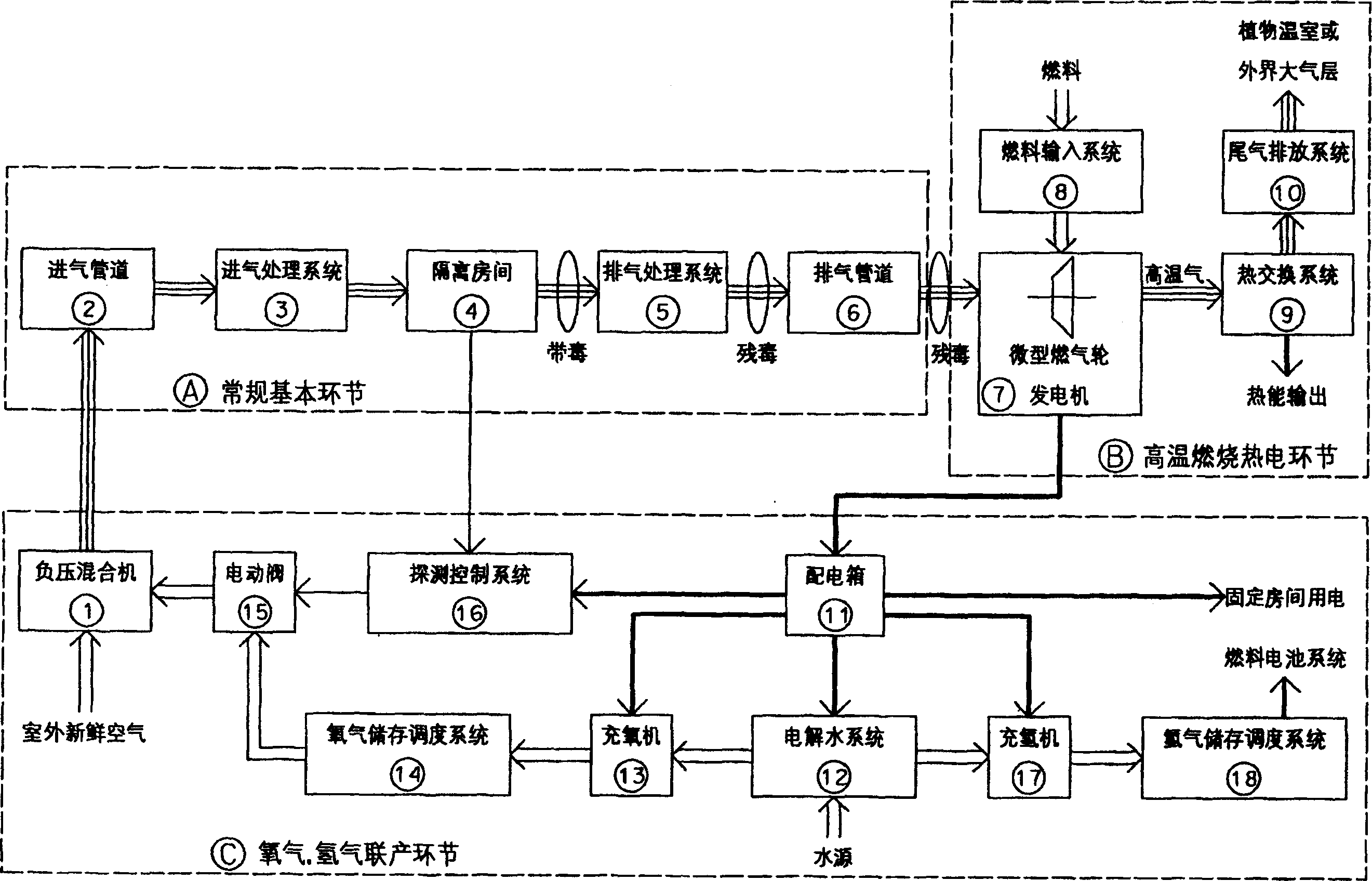
[0025] The composition of the high-temperature combustion cogeneration system of the isolation room exhaust of the present invention is as follows: figure 1 As shown, it consists of three parts: the first part A is the conventional basic link; the second part B is the high-temperature combustion thermoelectric link; the third part C is the oxygen and hydrogen cogeneration link.

[0026] 1. The part A in the figure is the routine basic link:

[0027] The intake pipe 2 is connected to the intake treatment system 3, the output of the intake treatment system 3 is connected to the isolation room (or room) 4, the output of the isolation room 4 is connected to the exhaust treatment system 5, and the output of the exhaust treatment system 5 is connected to the row Air pipe 6, exhaust pipe 6 communicate with the micro gas turbine generator 7 air inlet of B part.

[0028] 2. Part B in the figure is the high-temperature combustion thermoelectric link:

[0029] The exhaust pipe 6 is con...


PUM


Abstract

This invention is a joint system which is used for air exhaust of the isolating house. It is composed of three parts. The first part is conventional basic element. The second part is the high temperature burning pypoelectricity part. The third part is joint part of the hydrogen and oxygen.The second part includes gas turbine generator which has the combustion turbine and the dynamotor. The admission port is jointed with the air channel. The dynamotor of the gas turbine generator is connected with the distribution box in the third part. There are many lines in the third parts, which are connected with the detection control system, the electrolyzing water system, the machines used for adding oxygen and the electric connector used for adding hydrogen. It can remove the organic matter residual toxicity. In the same time, it can generate electricity and produce oxygen and hydrogen.

Description

technical field [0001] The invention relates to a treatment device for the exhaust of an isolation room, in particular to a high-temperature combustion cogeneration system for the exhaust of the isolation room. Background technique [0002] In today's hospital wards, especially the negative pressure isolation rooms for infectious diseases, before the internal toxic gas is discharged, it is generally sterilized by ultraviolet lamps in the exhaust pipe. There are many kinds of known bacteria and viruses, and unknown new bacteria and viruses may appear at any time. For the known poisonous gas, if only the short-term ultraviolet disinfection treatment of existing drugs and exhaust pipes is carried out from the ward or the laboratory (test), the luminous flux of the ultraviolet lamp will decline during long-term use, resulting in The intensity of ultraviolet light is reduced, which may not completely kill the virus. Even if a room can meet the corresponding biosafety protection...

Claims


Application Information

Patent Timeline
Patent Type & Authority Patents(China)
IPC IPC(8): F23G7/06A61L9/00
CPCY02E20/12
Inventor 吴晓海
Owner 吴晓海
Why Eureka
Try Eureka