
Spiral fractionation tower

A fractionation tower and spiral technology, applied in the field of oil separation equipment in the oil refining industry, can solve the problems of high cost, large investment, complex equipment, etc., and achieve the effect of low operating cost, low investment and uniform distribution

Inactive Publication Date: 2006-07-05
谢福胜
View PDF0 Cites 0 Cited by
  • Summary
  • Abstract
  • Description
  • Claims
  • Application Information

AI Technical Summary

Problems solved by technology

Especially for the current people in the use of waste plastics and waste rubber to refine oil, the equipment is complicated, the investment is large, and the cost is high, and there is no real output of qualified oil products in this field.

Method used


Image

  • Spiral fractionation tower
  • Spiral fractionation tower
  • Spiral fractionation tower

Examples


Embodiment Construction

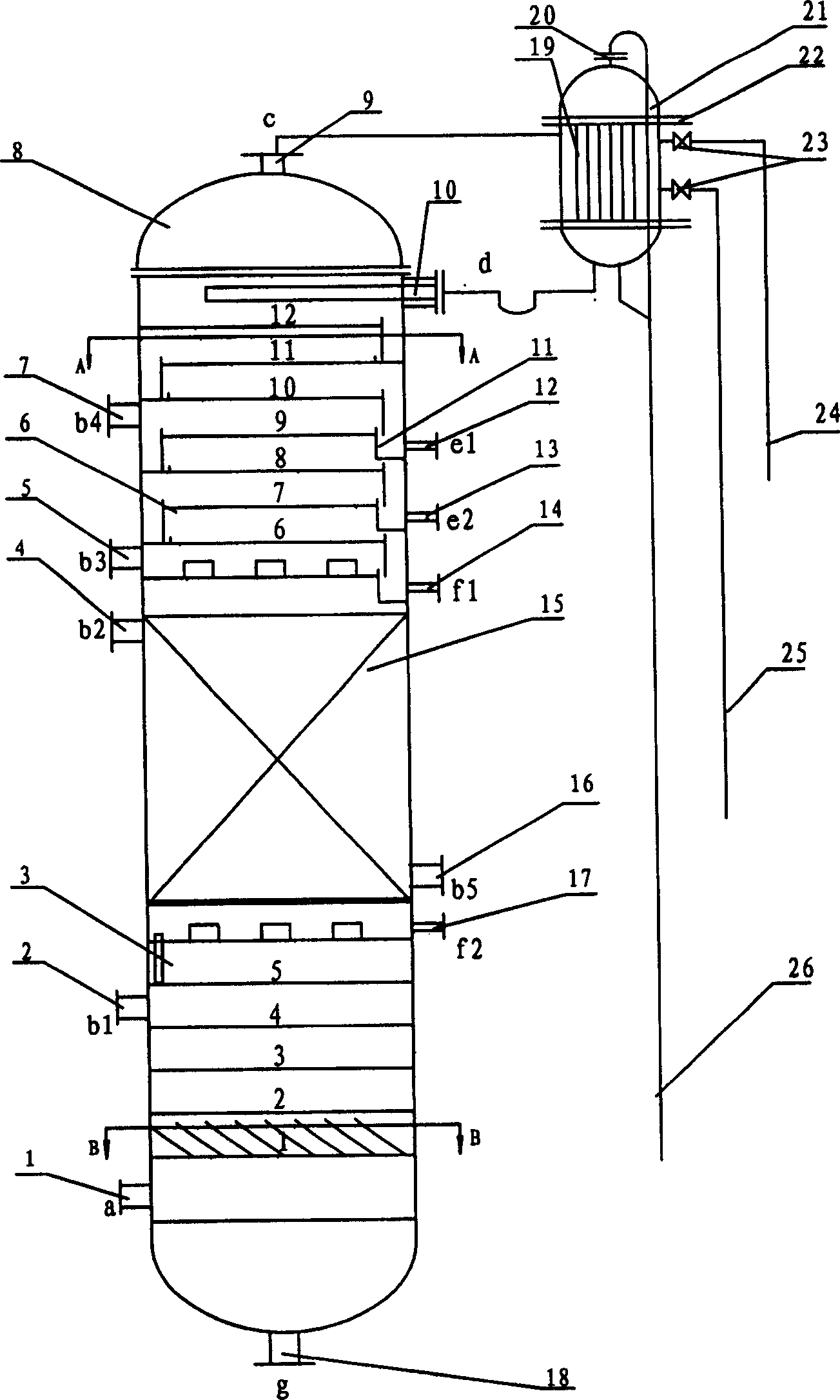
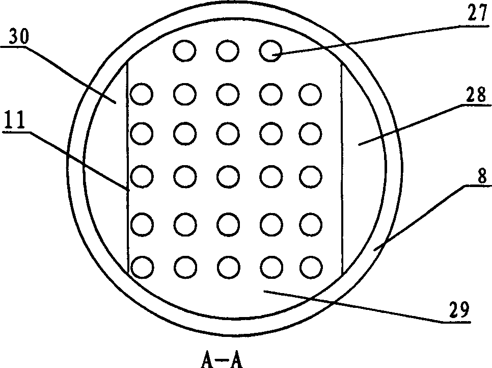
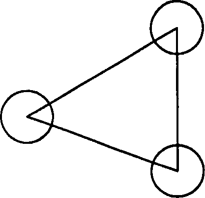
[0018] Below in conjunction with accompanying drawing, spiral fractionation tower of the present invention is described in further detail: as Figure 1-8 As shown, the interior of the spiral fractionation tower body 8 is divided into three sections, the tongue-shaped section is arranged as a tongue-shaped tray 3 in the lower part, and there are five layers of plate-shaped 1-5, and a plurality of tongue-shaped fins 31 are arranged at intervals on the upper part. One end of the fin 31 is fixed, and the other end is tilted to form a certain angle with the tongue-shaped tray 3, generally 20-60°, preferably 36° in the present invention, and the tongue-shaped tray 3 can be provided with multiple layers, preferably 5 layers. Each layer rotates at a certain angle relative to the next layer in parallel, generally 20-60°, preferably 36° in the present invention, 1-5 layers to 180° form a spiral channel, and the airflow rises 180° along the spiral channel. It is also possible to increase...


PUM


Abstract

The spiral fractional tower is characterized by that it includes tower body, in the interior of the tower body the lower portion tongue type section, middle portion packed section and upper portion floating valve section are respectively set. As compared with existent technology it can integrate the functions of component separation, decolourization and deodorization into one body, and its structure is simple and its operation cost is low.

Description

technical field [0001] The invention discloses a spiral fractionation tower, which belongs to the field of oil product separation equipment in oil refining industry. Background technique [0002] Conventional fractionation towers mainly include plate towers and packed towers, whose function is only to achieve component separation. Trace impurities in the product (which cause the product to have abnormal color and odor) must be removed through special decolorization and deodorization processes and equipment. Especially at present people are utilizing waste plastics, waste rubber in oil refinery, make equipment complicated, investment is big, cost is high, and also do not really output the qualified oil product at present in this field. Contents of the invention [0003] The technical problem to be solved by the present invention is: to overcome the deficiencies of the prior art, to provide a method that can not only realize the separation of components, but also realize th...

Claims


Application Information

Patent Timeline
Patent Type & Authority Patents(China)
IPC IPC(8): B01D3/32
Inventor 谢福胜
Owner 谢福胜
Learn More