
Roof thawing structure

A structure and roof technology, applied in building structure, roof, roof covering, etc., can solve problems such as ground subsidence, low thermal efficiency, unsatisfactory snow melting effect, etc.

Inactive Publication Date: 2006-05-10
ミサワ環境技術
View PDF0 Cites 0 Cited by
  • Summary
  • Abstract
  • Description
  • Claims
  • Application Information

AI Technical Summary

Problems solved by technology

[0003] However, due to the need to absorb a large amount of groundwater in the past snow melting methods, there is a danger of ground subsidence, and at the same time, problems of low thermal efficiency and unsatisfactory snow melting effect occur.

Method used


Image

  • Roof thawing structure
  • Roof thawing structure
  • Roof thawing structure

Examples


Embodiment Construction

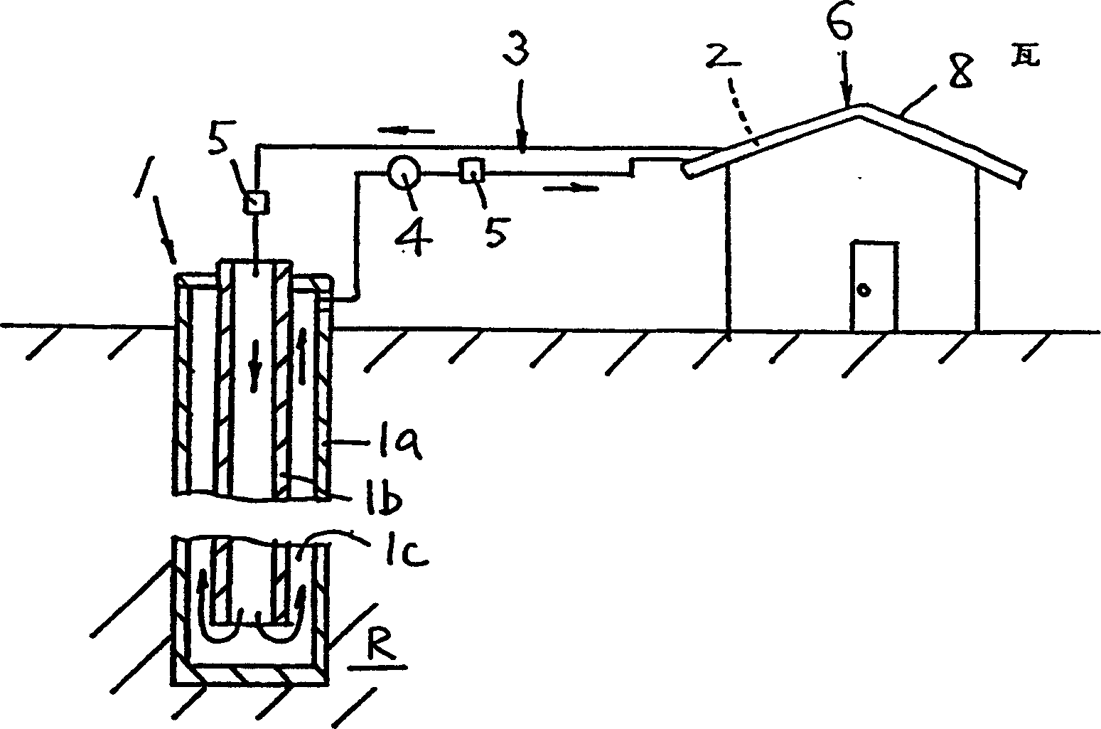
[0046] Regarding the embodiment of the first invention of the snow-melting roof structure, such as Figure 1 to Figure 4 shown. The structure of the snow-melting roof is to vertically bury the heat exchanger 1 that collects underground heat energy with antifreeze inside circulating in the ground, and transport the antifreeze liquid through the circulation pipe 3 to the heat radiation pipe 2 laid on the roof 6, and use the heat energy to melt the snow. Snow accumulation on roof 6.

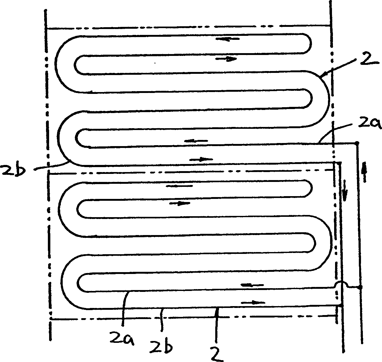
[0047] In this embodiment, the heat exchanger 1 is a concentric double pipe inserted into an inner cylinder 1b at the same center in an outer cylinder 1a with a closed lower end, and the lower end portion is buried in a rock layer R located 100m to 200m underground. And the heat release pipe 2 is formed by connecting the outgoing path 2a and the loop 2b end-to-end in the shape of a hairpin to ensure uniform heat dissipation throughout the whole length.

[0048] The above-mentioned heat radiation p...


PUM


Abstract

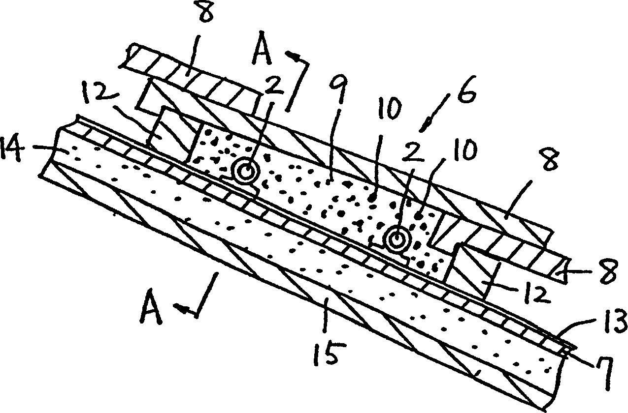
Provided is a structure of a snow-melting roof that can effectively melt accumulated snow without inducing the problem of ground subsidence. It is to vertically bury the heat exchanger (1) for collecting underground heat energy with antifreeze in the internal circulation, and to transport the circulation pipe (3) for transporting the antifreeze for collecting underground heat energy described above, and to transport the heat energy to the heat exchanger laid on the ground. The heat release pipe (2) of the roof (6) has a roof structure that uses this heat to melt the snow accumulated on the roof (6), and the pump (4) that circulates the antifreeze on the circulation pipe (3) and adjusts the flow of antifreeze The on-off valve (5) of the above-mentioned is laid on the roof slab (7), and the metal sheet (10) is mixed between the roof slab (7) and the tile (8). The repair soil (9), more lays copper plate (11) on the heat release pipe (2).

Description

technical field [0001] The present invention relates to roof constructions equipped with the function of melting snow. Background technique [0002] In order to deal with the accumulated snow on the roof, it is generally necessary to shovel off the accumulated snow by manpower climbing up the roof with tools such as shovels. This kind of work is accompanied by danger and requires more labor. In recent years, the method considered is to lay heat release pipes on the roof. Warm water drawn from the ground flows through the heat release pipes, and the heat energy of this warm water is used to achieve snow melting. Purpose. Contents of the invention [0003] However, due to the need to absorb a large amount of groundwater in the past snow melting methods, there will be a risk of ground subsidence, and at the same time, there will be problems of low thermal efficiency and unsatisfactory snow melting effect. [0004] The novel idea proposed by the present invention for the abo...

Claims


Application Information

Patent Timeline
Patent Type & Authority Patents(China)
IPC IPC(8): E04D13/00F28D3/02
Inventor 洲泽昭已
Owner ミサワ環境技術
Learn More