
Motor shaft for rotation/direct action converting motor and method of manufacturing the motor shaft

A technology of a motor shaft and a manufacturing method, which is applied in the field of rotary/direct conversion motors, can solve the problems of thread deviation, waste parts, and non-waste parts, etc., and achieves the effect of preventing position deviation and phase deviation.

Inactive Publication Date: 2006-03-29
MITSUBISHI ELECTRIC CORP
View PDF1 Cites 0 Cited by
  • Summary
  • Abstract
  • Description
  • Claims
  • Application Information

AI Technical Summary

Problems solved by technology

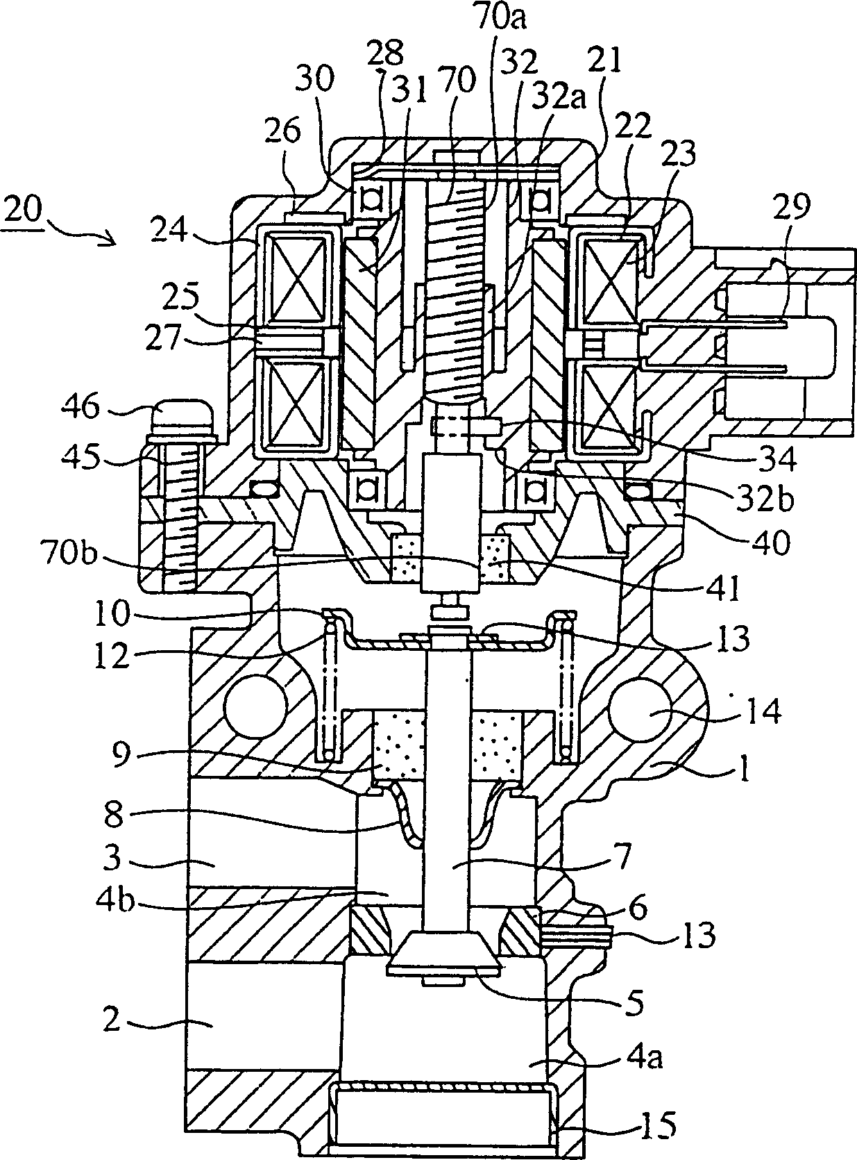
[0012] Conventional motor shafts for rotary / direct motion conversion motors have the above-mentioned structure, so positioning is difficult during roll forming, or the thread portion is deviated.
[0013] In addition, in order to align the phases of the threads, the anti-rotation part is formed with another member, and since the thread part and the anti-rotation part are fixed so that the phases of the threads coincide, there is a problem that the number of parts and the number of processing steps increase.
[0014] In addition, in this manufacturing method, since the method of cutting and forming from a round bar is adopted, there is a problem that the part removed during cutting, that is, the non-waste part discharged as chips increases.
[0015] In particular, when it is desired to form the anti-rotation part on the same member, it is necessary to use a round bar with a larger diameter for forming, so the wasteful part becomes more

Method used


Image

  • Motor shaft for rotation/direct action converting motor and method of manufacturing the motor shaft
  • Motor shaft for rotation/direct action converting motor and method of manufacturing the motor shaft
  • Motor shaft for rotation/direct action converting motor and method of manufacturing the motor shaft

Examples


Embodiment Construction

[0035] Hereinafter, in order to explain this invention in detail, the best form for carrying out this invention is demonstrated based on drawing.

[0036] Embodiment 1

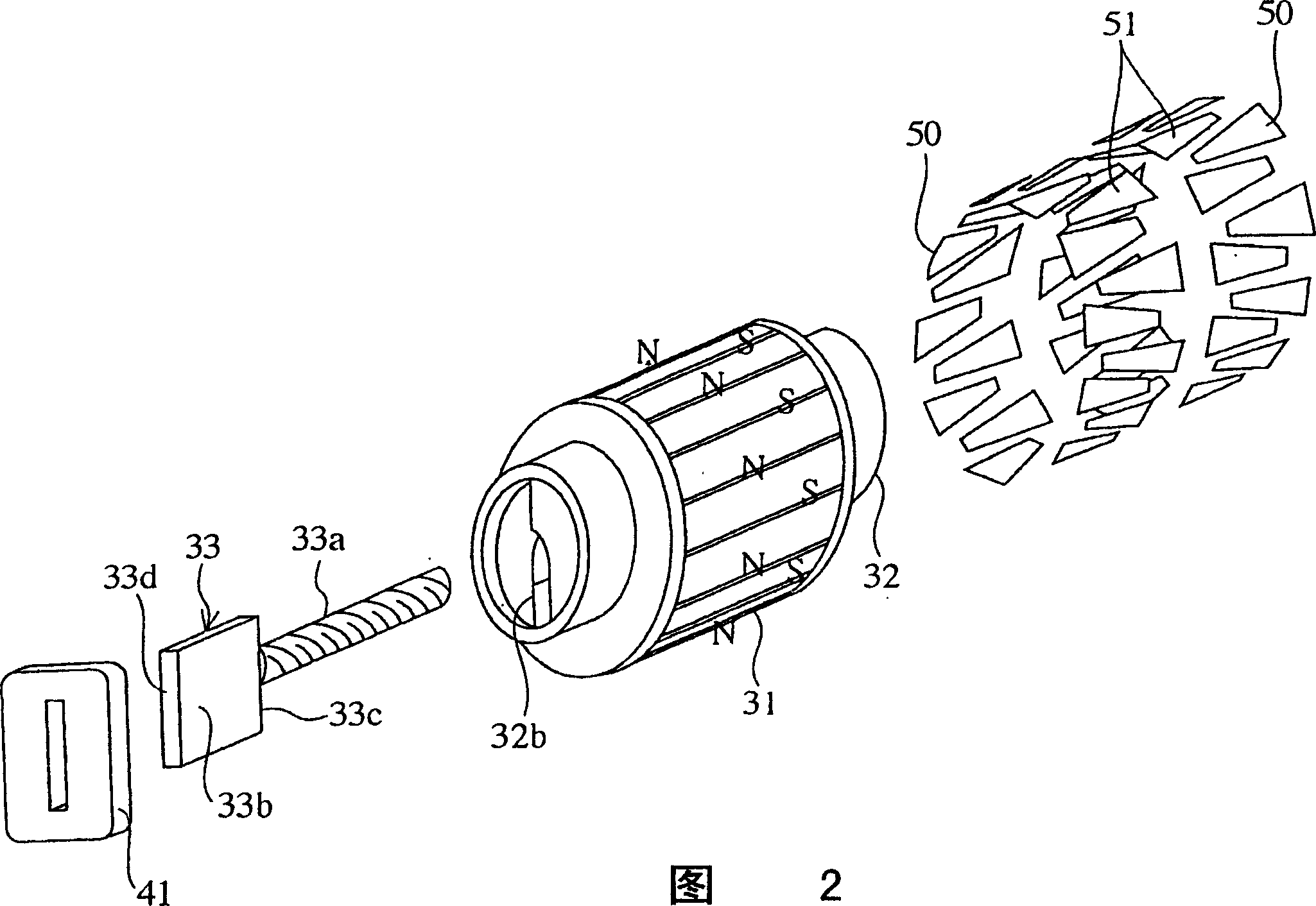
[0037] Fig. 2 is an exploded perspective view showing a main part of the rotary / linear conversion motor in the first embodiment.

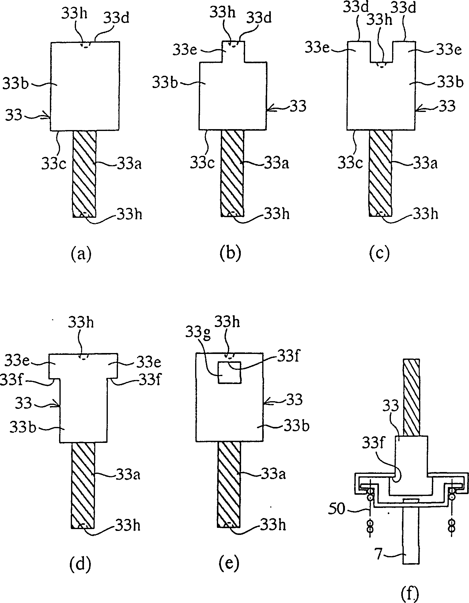
[0038] In this figure, 50 and 51 are stators such as iron cores wound with coils, 31 is a magnet composed of permanent magnets, etc., and 32 is a magnetic field generated by the flow of current in the stators 50 and 51. 32b is a stopper formed on the end surface of the rotor 32 on the valve shaft side to serve as a stopper on the motor side of the motor shaft 33 (described later). 33 is a motor shaft, which restricts the rotation of the motor shaft 33 in the direction of rotation around the shaft by engaging the threaded portion 33a with the rotor 32, engaging with the bushing 44 (described later), and a flat plate-shaped rotation restricting portion 33b; It is formed by the pr...


PUM


Abstract

A motor shaft for a rotational-to-direct motion converting motor has a rotation stopping portion formed in a plate shape, and a screw portion formed in a columnar shape. In addition, the motor shaft has a hole, arranged in an end portion of the motor shaft in a longitudinal direction of the motor shaft, for positioning the motor shaft in a form rolling. Therefore, a position shift or a phase shift of thread ridges formed on the screw portion can be prevented.

Description

technical field [0001] The present invention relates to the manufacture of a rotary / direct-acting conversion motor incorporating a mechanism for converting the rotary motion of the valve motor into a reciprocating motion (direct motion), which is used, for example, in a valve (EGR-V) of an exhaust gas recirculation system method. Background technique [0002] In the past, as disclosed in Japanese Invention Patent Publication No. 27023 of 1995, in the GER-V (exhaust gas recirculation control valve) control device, the rotation of the stepping motor (or linear motor) is converted into linear motion, and the EGR is driven. -V, adjust the opening of the valve to adjust the flow of recirculated exhaust gas. In addition, it describes a push type control valve in which a valve shaft is pushed by a motor shaft to open a valve, and a poppet type control valve in which a valve shaft is pulled by a motor shaft to open a valve. [0003] In addition, in Japanese Invention Patent Public...

Claims


Application Information

Patent Timeline
Patent Type & Authority Patents(China)
IPC IPC(8): H02K15/14H02K7/06
CPCF16H2025/204H02K7/06Y10T29/49789Y10T29/49995Y10T74/18664Y10T74/18688H02K15/14
Inventor 三好帅男横山永
Owner MITSUBISHI ELECTRIC CORP
Learn More