Steaming-boiling container for microwave oven

一种微波炉、容器的技术,应用在容器、刚性容器、微波加热等方向,达到容易浇铸并脱模、形状简单、避免液体沸腾溢出的效果

Inactive Publication Date: 2006-01-04
NEWSCHEF
View PDF1 Cites 0 Cited by
  • Summary
  • Abstract
  • Description
  • Claims
  • Application Information

AI Technical Summary

Problems solved by technology

Small openings or similar structures may be provided in certain parts of the container, but such openings may cause additional problems because they provide an entry point for dirt or dirt to enter the container

Method used


Image

  • Steaming-boiling container for microwave oven
  • Steaming-boiling container for microwave oven
  • Steaming-boiling container for microwave oven

Examples


Embodiment Construction

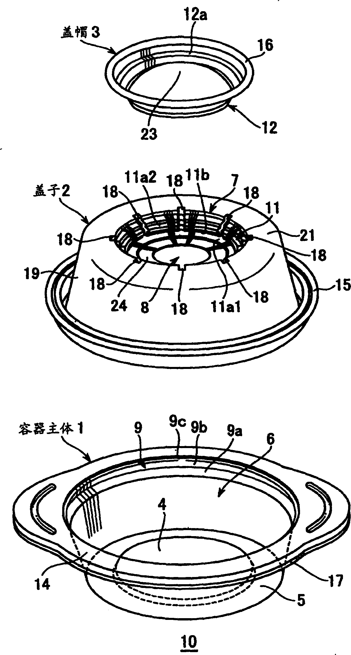
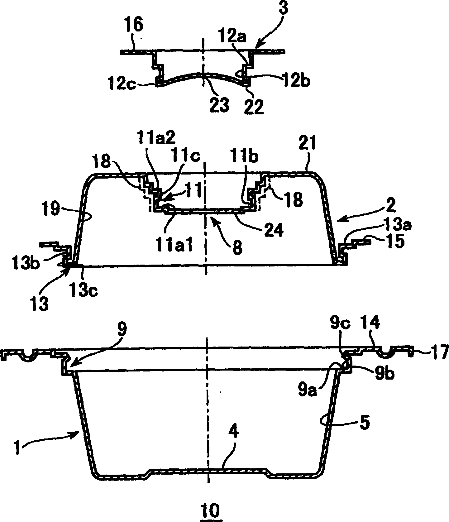
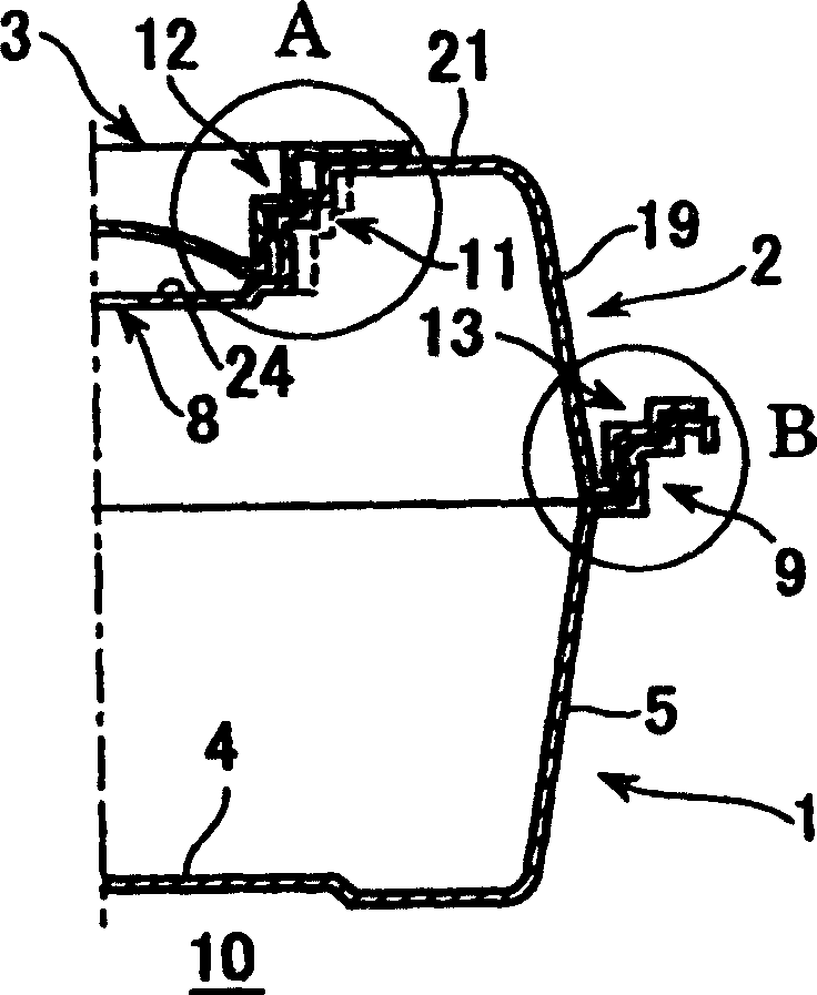
[0034] Such as figure 1 , 2 As shown, in the first embodiment, a container 10 includes a main body 1 , a lid 2 , and a cap 3 . The upper part of the body 1 has an annular inner shoulder forming a fitting 9 for receiving the annular lower part 13 of the lid 2 . A central recess 7 is formed in the upper part of the cover for receiving the cap 3 . The cap has an annular cap fitting portion 12 . The annular lower part 13 and the annular cap fitting part 12 cooperate with the fitting part 9 and the cap recess 7 respectively. The lid recess 7 has a central opening 8 and steam release grooves 18 formed in its side walls.

[0035] The recess 7 is conical with steps. When the cap 3 is accommodated in the recess 7, and the annular lower portion 13 at the bottom of the cap is accommodated in the upper fitting portion 9 of the main body 1, the liquid is prevented from boiling over or splashing. More preferably, the height of the cover 2 is equal to or greater than that of the main b...


PUM


Abstract

A container system for microwave oven cooking comprises a main body, a lid, and a cap disposed in a recess in the lid. The cap is movable upward and downward through a limited range in the recess depending on steam pressure, and grooves, formed in a side wall of the cap, or in a side wall of the recess, allow escape of steam when the cap is moved upward as a result of steam pressure. The lid is also allowed to move upward and downward relative to the main container body in response to steam pressure, and, when the lid is moved upward, an additional path for the escape of stem is provided at the location where the rims of the lid and main body meet each other.

Description

technical field [0001] The invention relates to a container for cooking in a microwave oven, in particular to a food container with a lid capable of automatically releasing thermal expansion steam. Background technique [0002] Microwave ovens are often used to heat food and beverages conveniently and easily. In the microwave heating of fresh food and processed food, a container made of a heat-resistant plastic plate with an airtight lid is widely used. Food and beverages can be contained in such containers and easily heated and steamed without removing them from the containers. [0003] Well-known microwavable containers have airtight lids and are capable of withstanding temperatures of about 120°C, which release the resulting expansion steam. The expanding steam can also escape through a groove in the fitting part of the container body when the lid is in place. Such a container is described in Japanese Patent No. 3009863. [0004] Problems are encountered with these c...

Claims


Application Information

Patent Timeline
Patent Type & Authority Patents(China)
IPC IPC(8): B65D81/34B65D43/08A47J36/38A47J27/00A47J36/02A47J36/06B65D21/02B65D43/02F24C7/02
CPCB65D81/3453B65D2543/00546B65D2543/00731B65D2543/0062B65D2543/00092B65D43/021B65D2543/00796B65D2543/00509B65D2543/00685B65D2543/00351B65D21/0237B65D2543/00296A47J36/027B65D81/3446H05B6/64B65D83/70
Inventor 大山义夫
Owner NEWSCHEF
Why Eureka
Try Eureka