Technique for producing laser welding stainless steel tubes cladded optic fiber unit

A stainless steel tube, laser welding technology, applied in laser welding equipment, welding equipment, manufacturing tools and other directions, can solve the problems of unreasonable distribution of optical fibers, uneven distribution of optical fibers, and the effective life of optical fibers cannot be guaranteed. Good consistency, uniform and stable excess length, and improved strength

Inactive Publication Date: 2005-11-02
JIANGSU ZHONGTIAN TECH CO LTD +1
View PDF0 Cites 0 Cited by
  • Summary
  • Abstract
  • Description
  • Claims
  • Application Information

AI Technical Summary

Problems solved by technology

The optical fiber units used in optical fiber composite overhead ground wire OPGW and submarine optical cable SOFC are due to various factors such as: unreasonable restrictions on production process methods, inconsistent state of optical fibers in stainless steel tubes, such as uneven distribution of optical fibers in stainless steel tubes, insufficient ointment filling, etc. Factors lead to unreasonable distribution of optical fiber in the tube in the optical fiber unit, so that the effective life of the optical fiber cannot be guaranteed. In addition, due to the limitations of existing equipment, existing products cannot meet the requirements of customers for ultra-long and large-core optical fiber units.

Method used


Image

  • Technique for producing laser welding stainless steel tubes cladded optic fiber unit
  • Technique for producing laser welding stainless steel tubes cladded optic fiber unit

Examples


Embodiment Construction

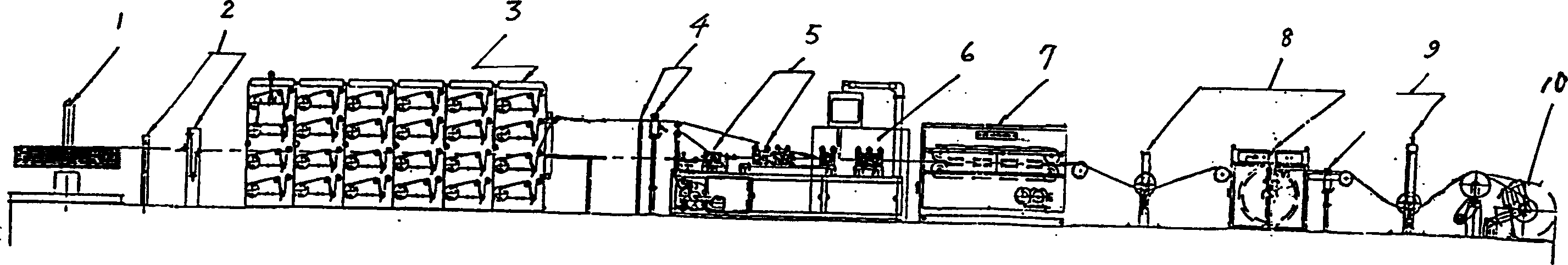
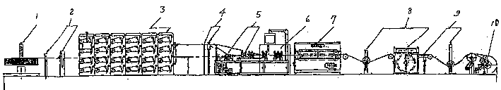
[0028] Refer to attached figure 1 , Laser welding stainless steel tube optical fiber unit production line Laser welding stainless steel tube optical fiber unit production line includes large-length optical fiber pay-off frame 3, oil-filled part 4, steel belt unwinding part, steel belt longitudinal wrapping and welding part 5, steel pipe drawing, on-line Weld seam detection part 6, traction and excess length control device 7, wire take-up device.

[0029] The large-length optical fiber pay-off stand 3 has a pay-off stand body, and several groups of single-disc fiber pay-off trays are arranged on both sides of the pay-off stand body, and a fiber guide slide bar is arranged beside the single-disk fiber pay-off tray. The disk is installed on the fiber optic disk shaft, the fiber optic disk shaft is installed on the double support bearing, and the fiber optic disk shaft end is equipped with a tension adjustable controller. The adjustable tension controller adopts a magnetic damper...


PUM


Abstract

The ivnention relates to the product line suitable to the optic fiber unit with the stainless steel tubes packed for optic fiber composite aerial earth wire OPGW and submarine fiber capable SOFC as well as its producing technique. The production line includes following sections: The feeding reel for long length of optical fiber, the oil charge, the unreeling steel tape, the longitudinal covering and welding etc. The producing steps are included as follows. unreeling optical fiber the optical fiber is introduced into the stainless steel tube, filling in salve to reduce friction force, unreeling steel tape, longitudinal covering type welding stainless steel tape drawing welded stainless steel tube containing fibers, traction and the residual length control, taking the optical fiber up.

Description

technical field [0001] The invention relates to a production process of laser welding stainless steel tube optical fiber unit and a production line thereof, which relate to a production line and production process of stainless steel tube optical fiber unit suitable for optical fiber composite overhead ground wire OPGW and submarine optical cable SOFC. Background technique [0002] The optical fiber unit used in the existing optical fiber composite overhead ground wire OPGW and submarine optical cable SOFC is mainly composed of a plastic tube PBT plus an aluminum tube. The optical fiber units used in optical fiber composite overhead ground wire OPGW and submarine optical cable SOFC are due to various factors such as: unreasonable restrictions on production process methods, inconsistent state of optical fibers in stainless steel tubes, such as uneven distribution of optical fibers in stainless steel tubes, insufficient ointment filling, etc. Factors lead to unreasonable distri...

Claims


Application Information

Patent Timeline
Patent Type & Authority Patents(China)
IPC IPC(8): G02B6/44
Inventor 薛济萍吴建华李海泉马赟张祝兵陆如泉
Owner JIANGSU ZHONGTIAN TECH CO LTD
Why Eureka
Try Eureka