Ball-shape non-electrode illuminating device

A lighting device, electrodeless technology, applied in lighting devices, components of lighting devices, cooling/heating devices of lighting devices, etc., can solve problems such as shortened lifespan

Inactive Publication Date: 2005-10-19
LG ELECTRONICS INC
View PDF0 Cites 0 Cited by
  • Summary
  • Abstract
  • Description
  • Claims
  • Application Information

AI Technical Summary

Problems solved by technology

Moreover, the lifetime is also shortened by the heat of the reflector 80

Method used


Image

  • Ball-shape non-electrode illuminating device
  • Ball-shape non-electrode illuminating device
  • Ball-shape non-electrode illuminating device

Examples


Embodiment Construction

[0045] The preferred embodiments of the invention will now be described in detail, examples of the invention being given in the accompanying drawings.

[0046] Components identical to those of the prior art are denoted by the same reference numerals.

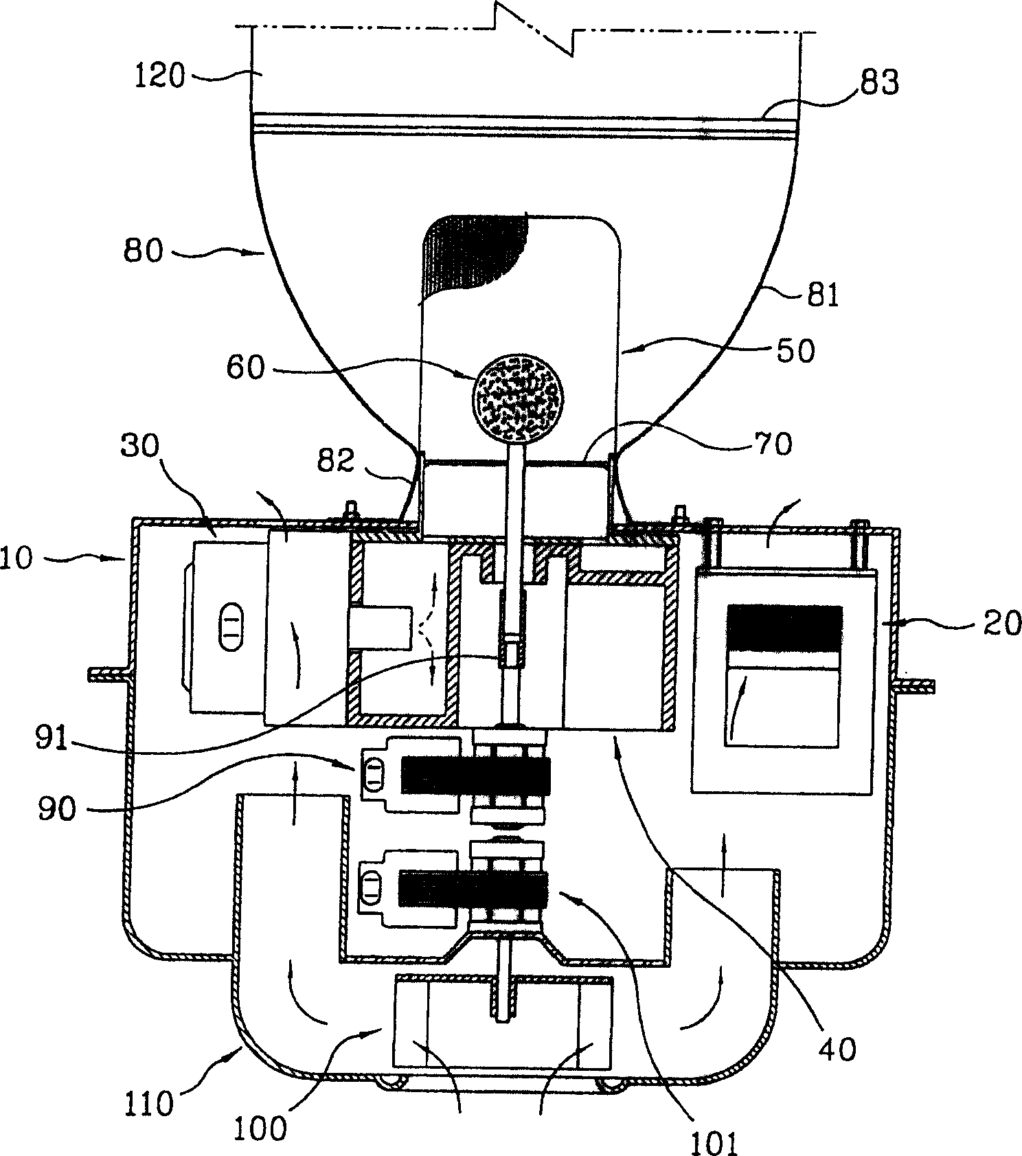
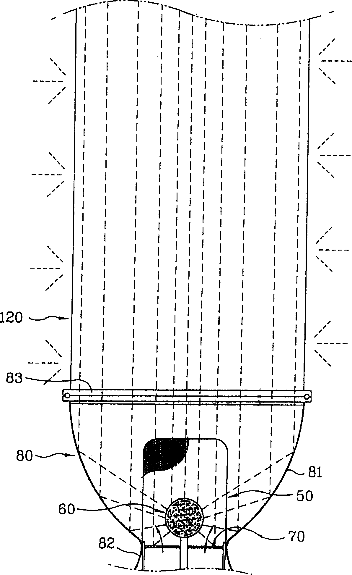
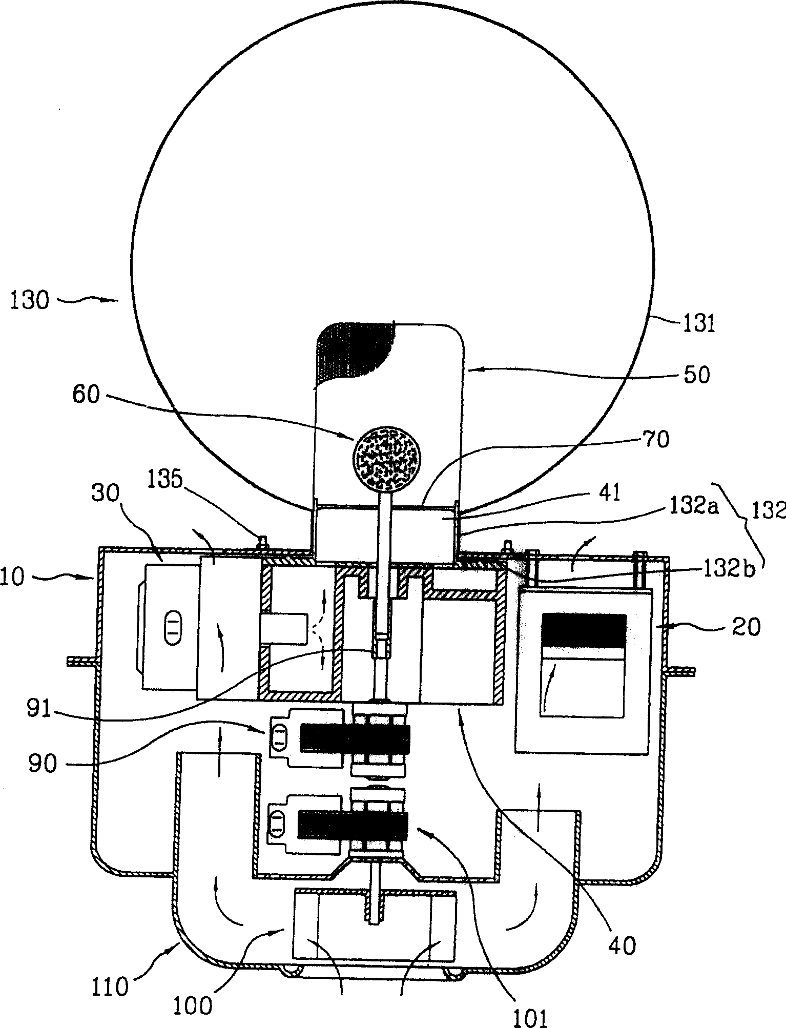
[0047] image 3 is a longitudinal sectional view of the electrodeless lighting device according to the first embodiment of the present invention.

[0048] As shown in the figure, the electrodeless lighting device according to the first embodiment of the present invention includes: a high voltage generator 20 which is arranged on the inner front surface of the housing 10 to generate a high voltage; The control tube 30 generates microwaves by transmitting the high voltage generated by the high voltage generator 20 .

[0049] In addition, a waveguide 40 for transmitting microwaves generated by the magnetron 30 is arranged between the magnetron 30 and the high-voltage generator 20, and a mesh 50 is installed on the outlet portion ...


PUM


Abstract

An electrodeless lighting apparatus using microwave comprises: a waveguide for transmitting microwave generated in a magnetron; a mesh screen coupled to an outlet portion of the waveguide for blocking a leakage of the microwave and passing light; a bulb located in the mesh screen for emitting light by generating plasma by the microwave; and a globe installed on outer area of the mesh screen so that the light generated in the bulb can be radiated to omnidirection, that is, the globe is installed around the bulb instead of a reflector and a light guide which are used in the conventional art, and thereby, a structure of the lighting apparatus can be made simply and an omnidirectional lighting can be performed.

Description

technical field [0001] The invention relates to an electrodeless lighting device, in particular to a spherical electrodeless lighting device which can expand the lighting range by adopting a simple structure. Background technique [0002] Generally, an electrodeless lighting device is a device that irradiates an electrodeless bulb with microwaves to generate visible light or ultraviolet light. In addition, the electrodeless lighting device has a longer life than conventionally used incandescent lamps or fluorescent lamps, and has better lighting effects. [0003] figure 1 A longitudinal sectional view of an electrodeless lighting device in the prior art is shown. [0004] As shown in the figure, the existing electrodeless lighting device includes: a housing 10; a high voltage generator 20 installed inside the housing 10 to generate high voltage; a magnetron 30 installed in the housing 10, which is connected to the high voltage generator The device ...

Claims


Application Information

Patent Timeline
Patent Type & Authority Patents(China)
IPC IPC(8): F21V29/00F21K2/00F21S2/00F21V3/00F21V3/02F21V3/04F21Y101/00H01J17/20H01J65/04H05B
CPCH01J65/044
Inventor 李在振永珍朴根永
Owner LG ELECTRONICS INC
Why Eureka
Try Eureka