A kind of LED light-emitting component and its lamp

A technology for LED lamps and light-emitting components, which is applied to semiconductor devices of light-emitting components, light sources, light source fixing, etc., can solve problems such as limited area, scrapped light-emitting components, lack of insulation withstand voltage, etc. Layer area, the effect of increasing the contact area

Inactive Publication Date: 2016-09-28
JIANGSU SUN & MOON LIGHTING +1
View PDF5 Cites 0 Cited by
  • Summary
  • Abstract
  • Description
  • Claims
  • Application Information

AI Technical Summary

Problems solved by technology

[0002] Traditional LED lighting components often can only achieve one-way lighting, such as figure 1 As shown, the LED light-emitting chip 4 is arranged on the surface of the substrate 3, and its light-emitting surface can only emit light in one direction toward the side away from the substrate.
[0003] Then the industry developed a full-circle light LED lighting component, such as Figure 2-1 As shown, the light-emitting component is provided with an aluminum substrate 100. The edge of the aluminum substrate 100 is provided with a number of upwardly protruding bending parts 110 along the same side. An LED light source 200 with bidirectional light emission. The LED light source 200 generally uses a transparent substrate 210 as the carrier of the LED light-emitting chip and is used to bond the bending portion 110 of the aluminum substrate 100. The material of the transparent substrate 210 is generally made of transparent glass or sapphire. Made of glass, which is a brittle material, and because the transparent substrate 210 and the bent portion 110 of the aluminum substrate 100 are pasted and fixed through the pad 220, because the area of ​​the pad 220 is limited, the light-emitting component will not Once uncontrollable factors such as collision, vibration, and impact occur during the process, the transparent substrate 210 bonded / welded on the bending part 110 through the pad is prone to breakage, resulting in the scrapping of the entire set of light-emitting components; at the same time, the light-emitting chip 230 is fixed. On the transparent substrate 210, since the transparent substrate 210 is made of transparent glass or sapphire glass, the material itself has no heat conduction effect, so the power of the LED light-emitting chip 230 set on it is small (generally no more than 0.2W), and cannot carry The application of high-power LED light-emitting chips; finally, due to the lack of insulation and withstand voltage design between the aluminum substrate 100 and the transparent substrate 210 in this technical solution, see Figure 2-2 , the conductive circuit 120 on the aluminum substrate 100 supplies power to the LED light-emitting chip 23' on the transparent substrate 210 through the pad 220, but since the pad 220 is to realize the bonding and fixing of the transparent substrate 210 and the bending part 110 of the aluminum substrate, It is also necessary to supply power to the LED light-emitting chip 230, so the area of ​​the pad 220 cannot be too small. However, due to the limited width of the bent portion 110 of the aluminum substrate 100, the longitudinal and transverse distances between the pad 220 and the bent portion 110 of the aluminum substrate will eventually be reduced. The boundary distance is too short, as shown in the figure, there is no creepage distance close to the boundary of the bending part 110 in the transverse direction, while the vertical creepage distance H' is too short, less than 2mm, so it is easy to produce high-voltage sparking phenomenon (see Figure 2-3 , Figure 2-4 ), fail to pass the insulation withstand voltage test

Method used


Image

  • A kind of LED light-emitting component and its lamp
  • A kind of LED light-emitting component and its lamp
  • A kind of LED light-emitting component and its lamp

Examples


Embodiment Construction

[0035] In order to further explain the technical solutions of the present invention, the present invention will be described in detail through specific embodiments below.

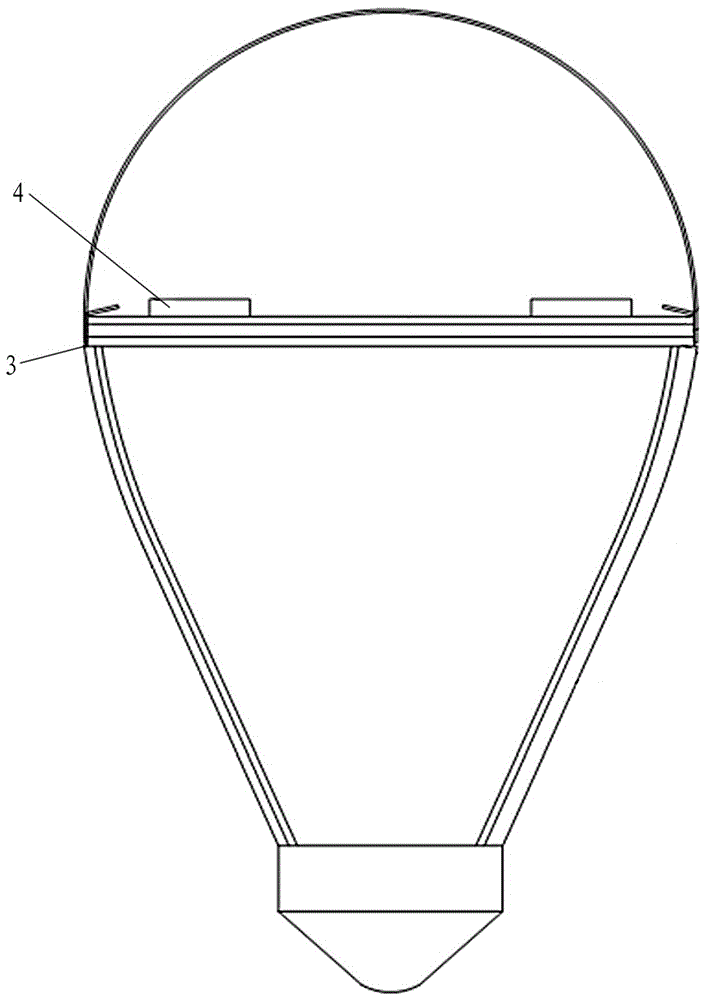
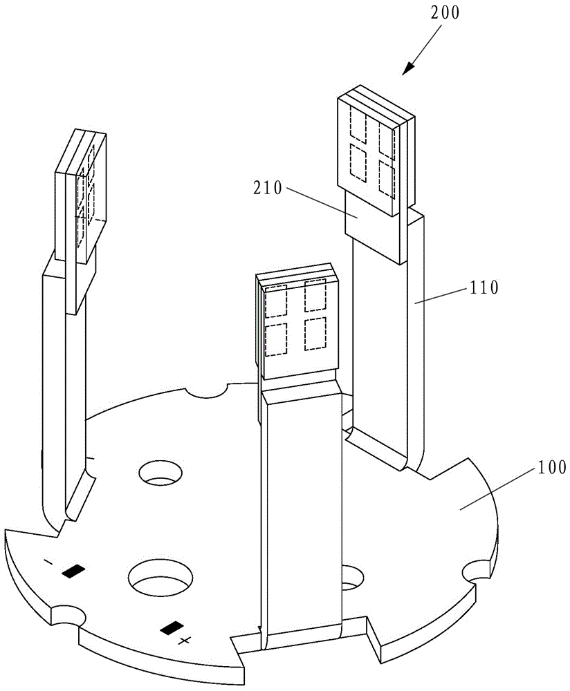
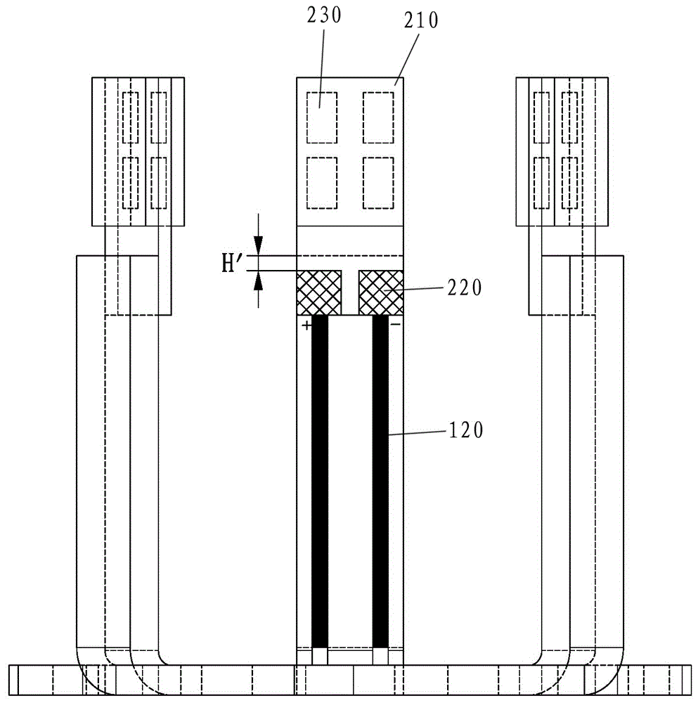
[0036] Such as Figure 3-1 to Figure 3-4 As shown, an LED lighting assembly includes an LED luminous body 1 with bidirectional light emission and an L-shaped bracket 2 for fixing the luminous body.

[0037] The bidirectional LED luminous body 1 includes a transparent substrate 11, an LED light-emitting chip 12 and a wavelength conversion layer 13. The transparent substrate 11 is made of transparent alumina or aluminum nitride ceramics. The material itself has certain thermal conductivity but does not have electrical conductivity. Its front and back surfaces are the first main surface 111 and the second main surface 112, respectively. A first conductive circuit 113 for supplying power to the LED light-emitting chip 12 is provided on a main surface. The LED light-emitting chip 12 is provided on the first main sur...


PUM


Abstract

The invention discloses an LED (light emitting diode) luminous subassembly. The LED luminous subassembly comprises an LED luminous body and an L-shaped support, wherein the LED luminous body can emit light in the double directions; the L-shaped support is used for fixing the luminous body and is made of materials with high heat-conduction characteristics; a U-shaped notch is formed in the middle of a vertical end of the L-shaped support; the LED luminous body which can emit light in the double directions is fixed with the support body on two sides of the U-shaped notch through a welding layer; and a luminous chip of the LED luminous body is correspondingly arranged on the U-shaped notch. By using the technical scheme, the structure stability on the LED luminous body and the support is improved, and the heat dissipation efficiency of the LED luminous body is improved. Moreover, the LED luminous subassembly is low in manufacturing cost, and can be widely applied to lamps such as bulb lamps and candle lamps.

Description

Technical field [0001] The invention relates to an LED light-emitting assembly, in particular to an LED light-emitting assembly capable of realizing full-peripheral illumination and a lamp used for the light-emitting assembly. Background technique [0002] Traditional LED lighting components can only achieve unidirectional light emission, such as figure 1 As shown, the LED light-emitting chip 4 is arranged on the surface of the substrate 3, and its light-emitting surface can only emit light in one direction away from the substrate. Its light-emitting angle is less than 180°, and its light intensity is concentrated in the middle and gradually attenuated around it. [0003] Then the industry developed a full-circle LED light-emitting component, such as diagram 2-1 As shown, the light-emitting assembly is provided with an aluminum substrate 100. The edges of the aluminum substrate 100 are provided with a plurality of upwardly protruding bending portions 110 along the same side. The to...

Claims


Application Information

Patent Timeline
Patent Type & Authority Patents(China)
IPC IPC(8): F21K9/00F21V19/00F21Y115/10
Inventor 徐向阳欧阳杰欧阳伟
Owner JIANGSU SUN & MOON LIGHTING
Why Eureka
Try Eureka