Vapor-deposited coating device for vacuum vapor-deposited coating apparatus

An evaporation and vacuum technology, used in vacuum evaporation plating, sputtering plating, ion implantation plating, etc., can solve the problems of danger, time-consuming, and large inertness in the adjustment of evaporation rate, and is conducive to control, high power consumption, etc. The effect of loss, small cost

Inactive Publication Date: 2005-06-01
APPLIED MATERIALS GMBH & CO KG
View PDF0 Cites 0 Cited by
  • Summary
  • Abstract
  • Description
  • Claims
  • Application Information

AI Technical Summary

Problems solved by technology

A further disadvantage of large-volume vapor deposition devices is that the adjustment of the vapor deposition rate is very inert, due to the high mass of such vapor deposition devices and the large mass of the metal to be evaporated in them, and because of the high mass of the vapor deposition devices. The temperature in the device can only be measured indirectly at the outer wall of the heating tube
An additional problem with such vapor deposition devices is that short maintenance cycles and insulation defects or ignited plasmas occur due to wear
Furthermore, melting new zinc and the necessary descaling and handling of liquid zinc is dangerous and time consuming

Method used


Image

  • Vapor-deposited coating device for vacuum vapor-deposited coating apparatus
  • Vapor-deposited coating device for vacuum vapor-deposited coating apparatus
  • Vapor-deposited coating device for vacuum vapor-deposited coating apparatus

Examples


Embodiment Construction

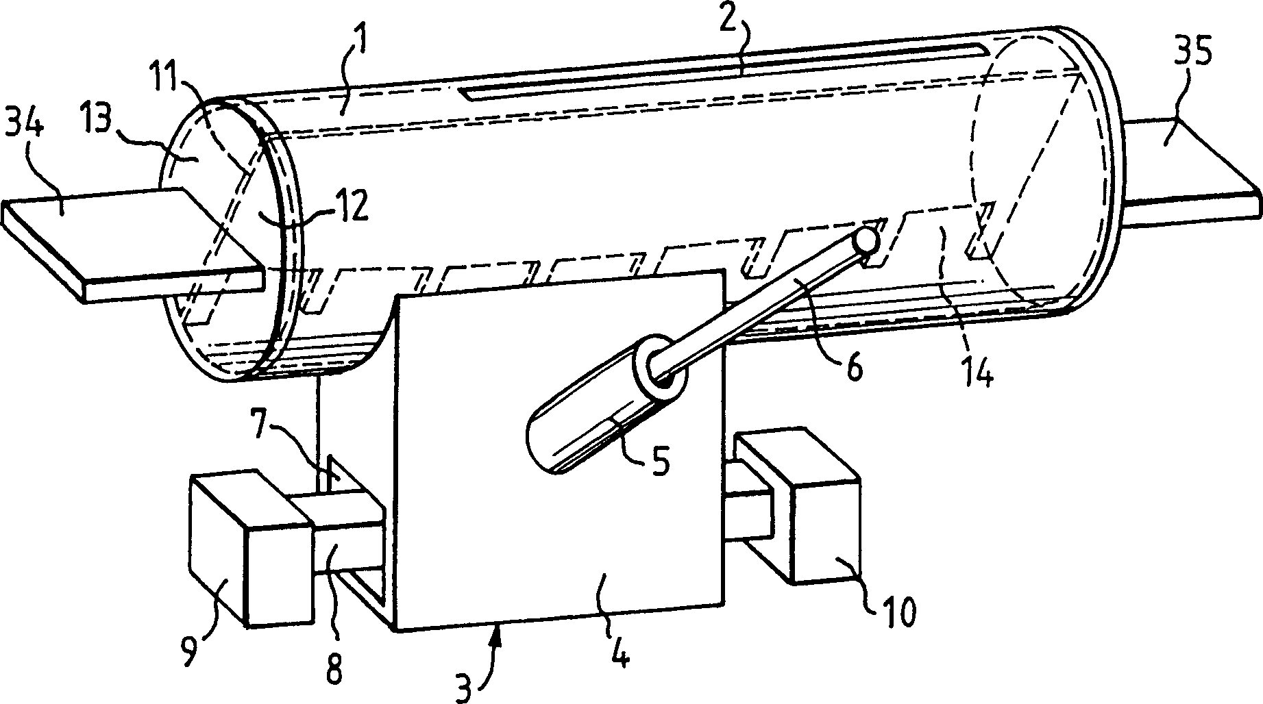
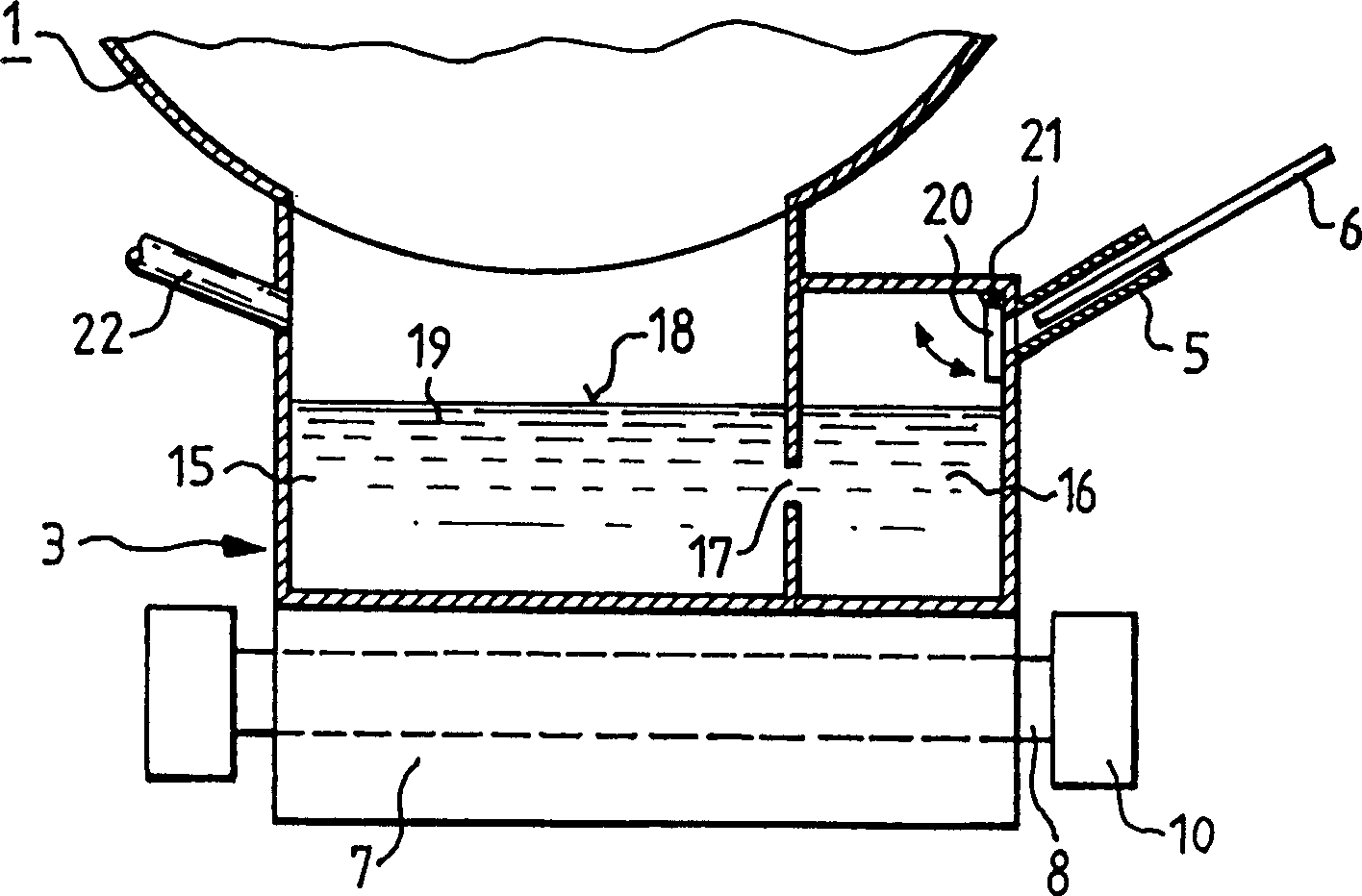
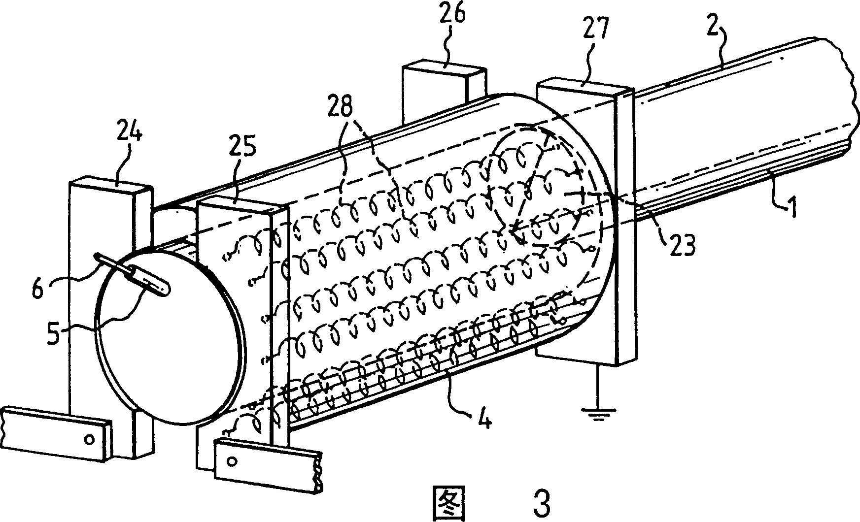
[0030] figure 1 The vapor deposition device shown as a whole in FIG. 2 is used in particular for the vapor deposition of zinc in coating systems and has a tubular nozzle body 1 . The nozzle body 1 has, on its outer surface, longitudinally extending nozzle slots 2 through which the steam for coating the film flows out during operation of the device. An evaporator 3 with a housing 4 is fastened to the underside of the nozzle body 1 . The evaporator housing 4 has an obliquely arranged feed pipe 5 through which the metal to be melted is fed into the evaporator 3 in the form of a wire 6 . For heating, the bottom of the evaporator housing 4 is designed as a steel pipe 7 with a rectangular cross-section, into which a heating rod 8 made of conductive ceramic penetrates. To heat the evaporator 3 , electrical energy flows through the heating rod 8 from one terminal 9 to the other terminal 10 of the heating rod 8 . The heating rod 8 here refers to a traditional boat-shaped evaporator....


PUM


Abstract

The vapor deposition device for a vacuum vapor deposition device has an evaporator ( 3 ) heated by an electric heating rod ( 8 ), which is connected to a nozzle body ( 1 ) designed as a hollow body. For vapor deposition, the steam flows from the evaporator (3) into the nozzle body (1) and from there out of the nozzle gap (2).

Description

technical field [0001] The invention relates to an evaporation device for vacuum evaporation equipment. The evaporation device has an evaporator heated by an electric heater and a nozzle body with a nozzle slit; the evaporator has a melting pot for evaporating the input metal, and the above-mentioned nozzle slit is used for discharging the generated metal steam. Background technique [0002] For evaporating eg aluminum, copper or other metals with a high melting point, a so-called evaporator boat is usually arranged in the vacuum chamber, which consists of electrically conductive ceramic and through which an electric current flows to evaporate the supplied metal. The boat-shaped evaporators respectively pass through the car slots to form melting pots for the metal to be evaporated. In this case, the cavity above the evaporator boat is completely open, so that the metal evaporated therein reaches directly onto the film passing above the evaporator boat, where it can be depo...

Claims


Application Information

Patent Timeline
IPC IPC(8): C23C14/26C23C14/24
CPCC23C14/24C23C14/243C23C14/246
Inventor G·科勒姆H·诺德特W·阿赫特纳
Owner APPLIED MATERIALS GMBH & CO KG
Why Eureka
Try Eureka