Work-clamping means

A fixture and main body technology, applied in the direction of clamping, clamps, manufacturing tools, etc., can solve the problems of workpiece loosening, not setting, disappearing, etc.

Inactive Publication Date: 2005-04-06
SMC CORP
View PDF1 Cites 0 Cited by
  • Summary
  • Abstract
  • Description
  • Claims
  • Application Information

AI Technical Summary

Problems solved by technology

[0005] However, the clamping cylinder disclosed in U.S. Patent No. 4,458,889 related to the above-mentioned prior art is not provided with such a mechanism that, for example, when a workpiece not shown in the figure is clamped by the arm 8, for whatever reason, if The work of supplying pressurized fluid to the cylinder 1c is stopped, and neither is provided with a mechanism for maintaining the clamped state of the workpiece
Therefore, there is a fear that the clamped state of the workpiece will disappear and the workpiece may be loosened

Method used


Image

  • Work-clamping means
  • Work-clamping means
  • Work-clamping means

Examples


Embodiment Construction

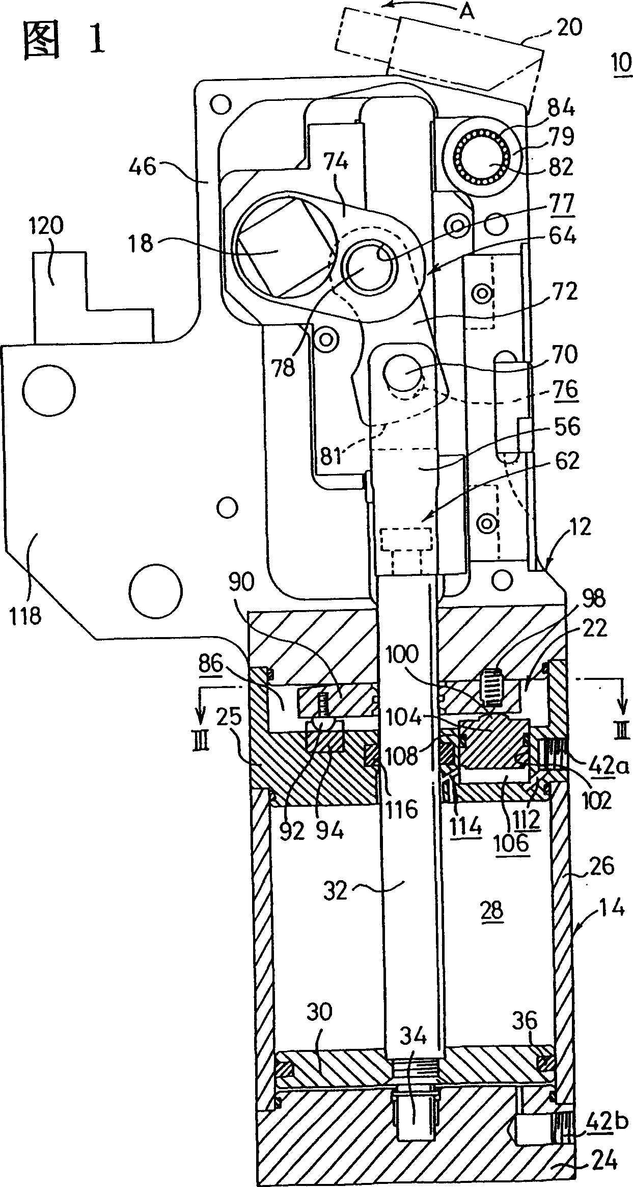
[0021] FIG. 1 shows a clamp 10 according to an embodiment of the present invention. The clamp 10 comprises: a main body 12; a cylinder part (drive mechanism) 14 connected in a sealed manner to the lower end of the main body 12; an arm 20 connected to a support part 18 having a rectangular cross-section through which protruding outside through a pair of substantially circular openings (not shown) formed through the main body 12;

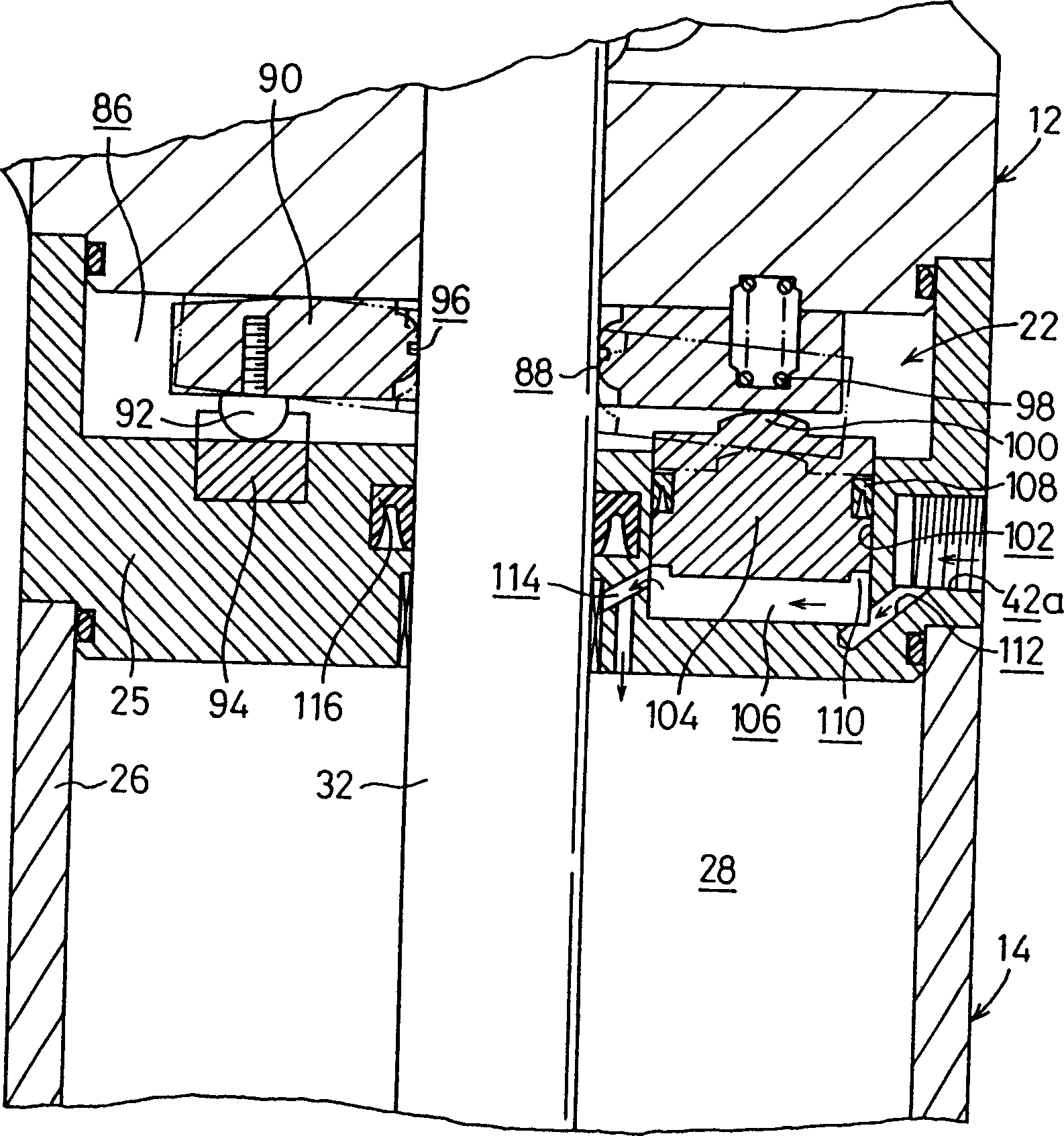
[0022] Cylinder portion 14 comprises an end block 24 and a generally cylindrical member of oval cross-section, and the cylinder portion comprises a cylinder 26, the first end of which is sealed with the recess of end block 24. connection, the second end of which is connected in a sealed manner to a block-shaped element 25 constituting the locking mechanism 22 .

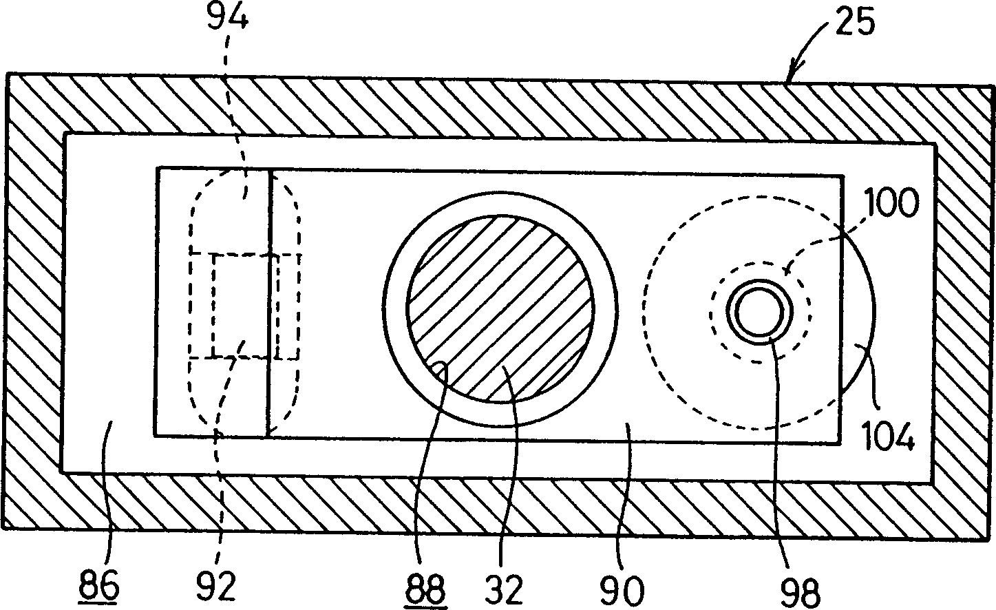
[0023] The pressure cylinder part 14 also includes: a piston 30 housed in the cylinder 26, which reciprocates along the cylinder chamber 28; move. like image 3 As shown, the cross-sectio...


PUM


Abstract

Disclosed is a clamp apparatus comprising a cylinder section (14) for displacing a rod member (32) provided at the inside of a body (12) in an axial direction; a toggle link mechanism (64) for converting rectilinear motion of the rod member (32) into rotary motion; an arm (20) for making rotation by a predetermined angle in accordance with a driving action of the cylinder section (14); and a lock mechanism (22) for maintaining a clamped state of a workpiece effected by the arm (20) even when transmission of driving force of the cylinder section (14) to the arm (20) is stopped.

Description

technical field [0001] The present invention relates to a jig capable of clamping a workpiece by means of an arm that is rotatable by a predetermined angle according to the driving action of a driving mechanism. Background technique [0002] Previously, when welding structural parts of motor vehicles or the like, clamping cylinders were used, for example, to clamp the structural parts. Such a clamping cylinder is disclosed, for example, in US Pat. No. 4,458,889. [0003] Figure 9 and 10 The structure of the clamping cylinder disclosed in US Patent No. 4,458,889 is shown. That is, a piston rod 2 movable back and forth according to the driving action of the cylinder 1c is provided between the pair of separated bodies 1a, 1b. A connector 3 is connected to the first end of the piston rod 2 . A pair of link members 5 a, 5 b and a pair of rollers 6 a, 6 b are rotatably connected to both side portions of the connector 3 by means of a first shaft 4 . An arm 8 is rotatably conn...

Claims


Application Information

Patent Timeline
Patent Type & Authority Patents(China)
IPC IPC(8): B23Q3/06B25B5/12B25B5/16F15B15/06
CPCB25B5/122B25B5/16B23Q3/06
Inventor 高桥英仁高桥一义
Owner SMC CORP
Why Eureka
Try Eureka