Yarn adjusting head

A technology for thread adjustment and thread head, which is applied in the field of thread head adjustment, which can solve the problems of energy loss, inability of thread adjustment head to work stably, and inability to overcome the tension of the reset spring, etc., and achieve the effect of reasonable structural design and high stability

Pending Publication Date: 2020-01-03
泉州全能智控机械研究所有限公司
View PDF0 Cites 0 Cited by
  • Summary
  • Abstract
  • Description
  • Claims
  • Application Information

AI Technical Summary

Problems solved by technology

The disadvantage of this structure is that the closing action of the scissors (C3) is completed entirely by the tension of the return tension spring (C2), so the return tension spring (C2) must have a certain strength, if the tension of the return tension spring (C2) is insufficient, it cannot The scissors (C3) are driven to close completely, so the yarn (A) cannot be cut, and the knitting work cannot be completed smoothly. If the tension of the tension spring is strengthened, the piston rod in the starting cylinder (C1) will not be able to overcome the reset tension spring (C2) tension problem, so that the scissors (C3) cannot be fully opened, because the piston rod in the cylinder needs to overcome the tension of the reset extension spring (C2) when pushing the scissors (C1) to open, resulting in energy loss, the scissors ( C1) If it is not fully opened, the reset yarn feeder (C4) cannot send the yarn (A) into the scissors (C31) for cutting
Therefore, under the condition that the commonly used pressure in the textile field is 0.6-0.7mpa, the thread adjustment head of this design cannot work stably.

Method used


Image

  • Yarn adjusting head
  • Yarn adjusting head
  • Yarn adjusting head

Examples


Embodiment Construction

[0036] The present invention is described in detail below in conjunction with accompanying drawing description:

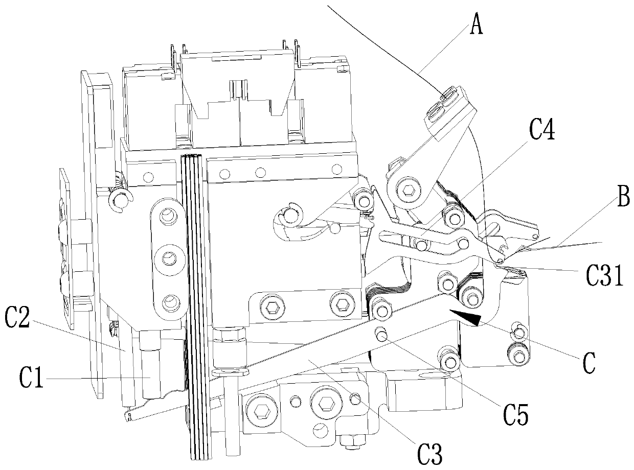
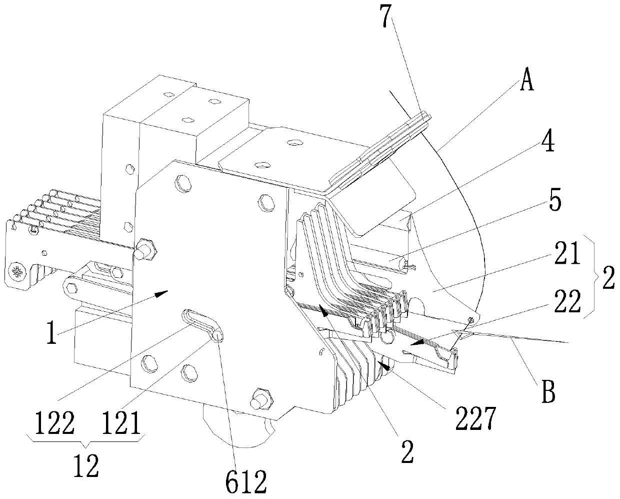
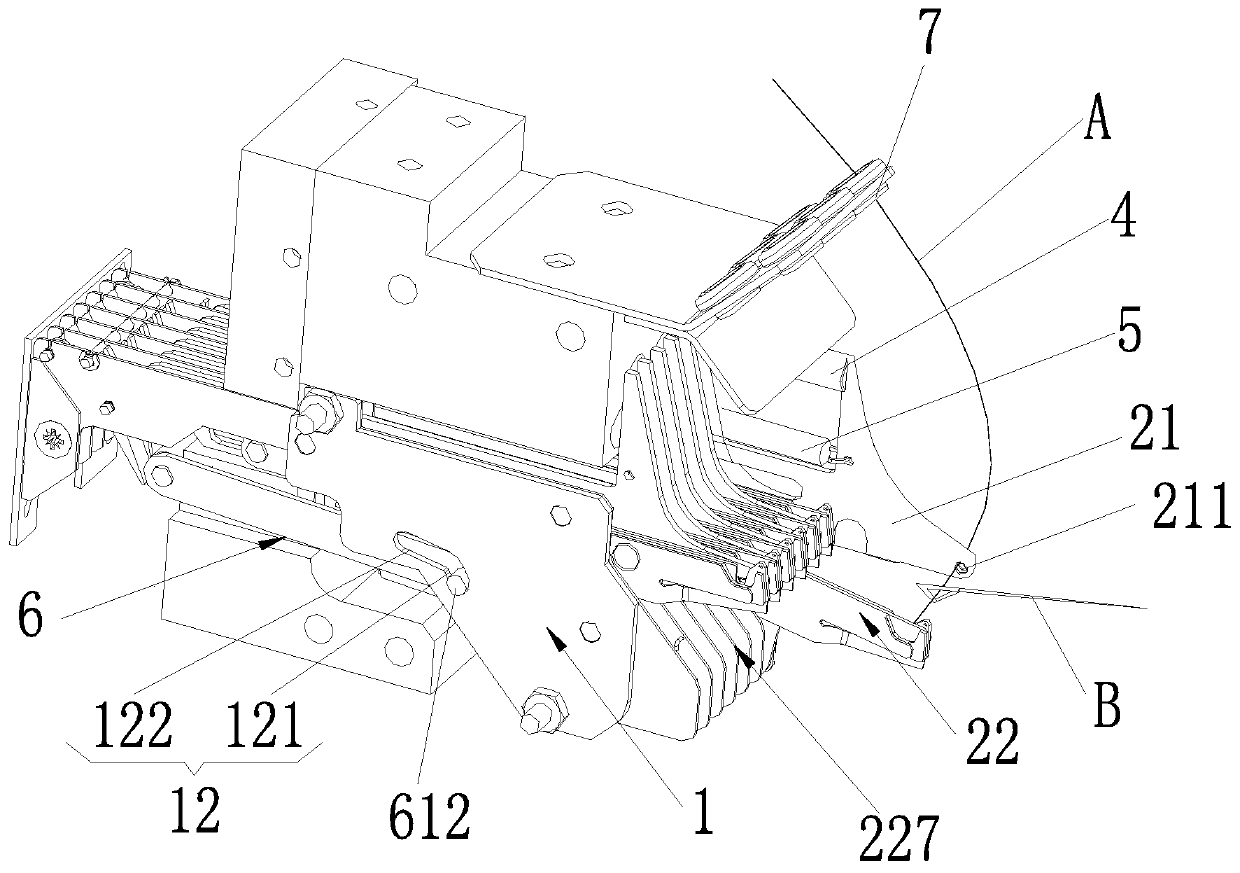
[0037] Such as Figure 2-10 As shown, a thread adjusting head of the present invention is characterized in that it includes a base 1 and more than one set of thread adjusting mechanisms 2 arranged on the base 1, and each set of thread adjusting mechanisms 2 includes a yarn feeder plate 21 and a yarn feeder Plate 21 cooperates with the scissors assembly 22 that is set, the front end of the yarn feeder plate 21 is provided with a threading hole 211, the free end of the yarn A passes through the threading hole 211 and is clamped and fixed on the scissors assembly 22. The yarn feeder plate 21 is slidably connected to the base 1 and can slide back and forth relative to the base 1, and the rear end of the yarn feeder plate 21 is provided with a first slot 212 extending in the front and rear direction, and the rear end of the scissors assembly 22 A first pin shaft 221 ma...


PUM


Abstract

The invention relates to a yarn adjusting head, comprising a base and more than one yarn adjusting mechanism unit; each yarn adjusting mechanism unit comprises a yarn nozzle plate and a scissor assembly matched with the yarn nozzle plate, a first pin shaft matched with a first slotted hole is arranged at the rear end of each scissor assembly, the first pin shaft at the rear end of the corresponding scissor assembly is connected with the corresponding first slotted hole at the rear end of the yarn nozzle plate in a matched manner, and the front end of each scissor assembly is connected with a base through a guide assembly; the yarn adjusting head further comprises a first resetting assembly connected between the base and the yarn nozzle plate; the yarn adjusting head further comprises a driving device for driving the scissor assemblies to loosen or cut off a yarn. The novel yarn adjusting mechanism is started by the yarn adjusting head, so that yarns can be stably exchanged for knittingneedles on a knitting machine, and the yarns can be clamped and cut at the end of yarn weaving to prepare for subsequent yarn adjusting.

Description

technical field [0001] The invention relates to the field of textile machinery equipment, in particular to a thread adjusting head. Background technique [0002] In the field of textile machinery and equipment, thread adjustment refers to the ability to change the yarn (A) for the knitting needle (B) on the knitting machine, so that the changed yarn (A) is hooked by the knitting needle (B) for weaving, and in a certain A device that can clamp and cut the yarn (A) at the end of the yarn (A) weaving, so as to prepare for the next thread adjustment work. The existing thread adjustment head is mostly used such as figure 1 As shown in the structure, the existing thread adjusting mechanism (C) of the thread adjusting head is driven by the starting cylinder (C1), and the return spring (C2) is used as the reset device. When a certain type of yarn (A) is finished knitting At the same time, the piston rod in the starting cylinder (C1) overcomes the pulling force of the return tensio...

Claims


Application Information

Patent Timeline
Patent Type & Authority Applications(China)
IPC IPC(8): D04B15/56D04B15/60D04B15/48
CPCD04B15/48D04B15/565D04B15/60
Inventor 张志勇张镇宏
Owner 泉州全能智控机械研究所有限公司
Why Eureka
Try Eureka