Auxiliary welding clamp for mechanical design and manufacturing

An auxiliary fixture and mechanical design technology, applied in welding/cutting auxiliary equipment, manufacturing tools, auxiliary devices, etc., can solve the problems of precision workpiece damage, uncontrollable clamping force, and inability to maintain the clamping state for a long time, to achieve The control operation is simple and the effect of limiting the clamping force is good

Pending Publication Date: 2021-06-15
XUZHOU COLLEGE OF INDAL TECH
View PDF6 Cites 0 Cited by
  • Summary
  • Abstract
  • Description
  • Claims
  • Application Information

AI Technical Summary

Problems solved by technology

[0003] When the current welding auxiliary fixture fixes parts, the clamping force is uncontrollable, which is easy to cause damage to some precision workpieces; in addition, the existing welding auxiliary fixture is easy to loose during welding, and cannot maintain the clamping state for a long time

Method used


Image

  • Auxiliary welding clamp for mechanical design and manufacturing
  • Auxiliary welding clamp for mechanical design and manufacturing
  • Auxiliary welding clamp for mechanical design and manufacturing

Examples


Embodiment

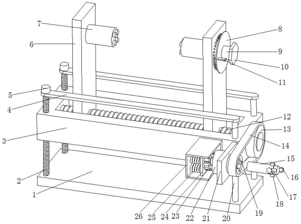
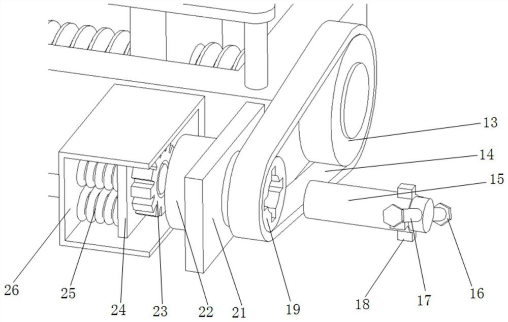
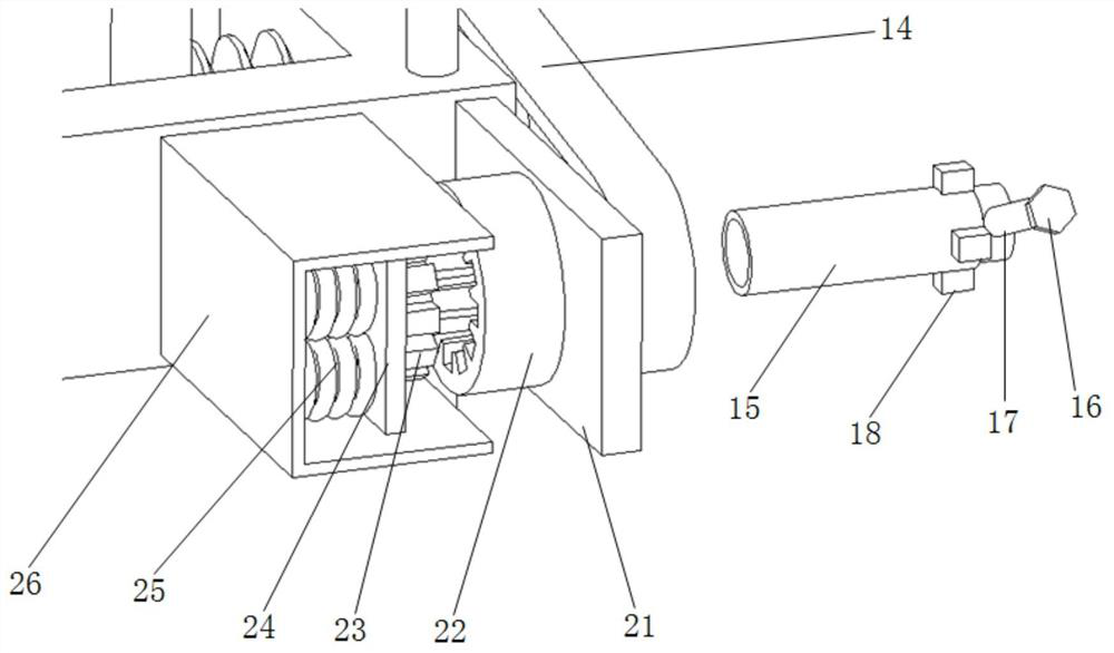
[0026] A welding auxiliary fixture for mechanical design and manufacture, such as Figure 1-4 As shown, it includes a return table 3, a double-ended screw 12, a console, a sleeve 15 and two clamping plates 6;

[0027] The two clamping plates 6 are arranged symmetrically in the 3 slots of the writing platform; further, the upper part of each clamping plate 6 is set with a clamping platform 7 through an angle adjustment device, such as Figure 4 As shown, each group of angle adjustment devices includes a limit plate 8, a rotating shaft 9 and a clip 11; one side of the upper part of the clamping plate 6 is provided with a clamping table 7 for rotation, and the other side is provided with a rotation shaft 9; The limit disk 8 is fixedly arranged on the rotating shaft 9; the other side of the upper part of the clamping plate 6 is provided with several square grooves along the circumference, and the limit disk 8 is provided with a through groove matching with the square groove; the c...


PUM


Abstract

The invention provides an auxiliary welding clamp for mechanical design and manufacturing. The auxiliary welding clamp comprises a concentric-square-shaped table, a double-thread screw, a control table, a sleeve and two clamping plates. The two clamping plates are symmetrically arranged in a concentric-square-shaped table groove; the double-thread screw penetrates through the lower ends of the two clamping plates respectively; the control table comprises a large belt wheel and a fixed groove; the large belt wheel is in transmission connection with the double-thread screw; a frame plate is fixedly arranged at the end of one side of the concentric-square-shaped table, a limiting shaft is rotationally arranged at one side, and a small belt wheel is arranged at the other side; the small belt wheel and the large belt wheel are synchronized through a synchronous belt; a cross-shaped groove is formed in the small belt wheel, and four clamping blocks matched with the cross-shaped groove are fixedly arranged in the circumferential direction of the sleeve; a tooth-shaped groove is formed in the limiting shaft; and a movable plate is arranged in the fixed groove in a sliding manner, a tooth-shaped block is fixedly arranged at one side of the movable plate, and the other side of the movable plate is connected with the bottom of the fixed groove through a plurality of springs. According to the auxiliary welding clamp, the clamping plates can be manually controlled to clamp a workpiece to be welded, the clamping force is autonomously controlled, the clamping state is maintained through a mechanical mechanism, and the state is controllable.

Description

technical field [0001] The invention relates to the technical field of mechanical manufacturing, in particular to a welding auxiliary fixture for mechanical design and manufacturing. Background technique [0002] Welding technology is often used in the process of mechanical design and manufacturing. Welding technology is used to weld different weldments to make the connection more stable and increase its durability. Therefore, welding auxiliary fixtures are widely used. [0003] When the current welding auxiliary fixture fixes parts, the clamping force is uncontrollable, which is easy to cause damage to some precision workpieces; in addition, the existing welding auxiliary fixture is easy to loose during welding, and cannot maintain the clamping state for a long time. [0004] For this reason, the present invention proposes a welding auxiliary jig for mechanical design and manufacture. Contents of the invention [0005] In order to solve the above problems, the object of ...

Claims


Application Information

Patent Timeline
IPC IPC(8): B23K37/04
CPCB23K37/0443
Inventor 席凤征徐敏
Owner XUZHOU COLLEGE OF INDAL TECH
Why Eureka
Try Eureka