
Assemby device

An assembly device and assembly table technology, which is applied in electrical components, semiconductor/solid-state device manufacturing, circuits, etc., can solve the problems of reduced assembly accuracy, limited device refitability, configurability and accessibility, deterioration, etc. The large amount of parts loaded per unit time is beneficial to accessibility and the effect of improving the speed of loading parts

Inactive Publication Date: 2005-03-02
SIEMENS ELECTRONICS ASSEMBLY SYST LLC
View PDF0 Cites 0 Cited by
  • Summary
  • Abstract
  • Description
  • Claims
  • Application Information

AI Technical Summary

Problems solved by technology

However, it has disadvantages: increased speed brings lower assembly accuracy
However, they have disadvantages: the applied and currently known rack technology together with the assembly movements to be realized either takes up too much space, that is to say reduces the available space on the assembly table, or worsens or limits the reconfigurability of the device or Configurability and accessibility
In addition, in order to achieve a high assembly accuracy under the corresponding high movement speed to achieve a high loading amount per unit time, the problem of sufficient rigidity of the known pressure welding machine structure has not been satisfactorily resolved.

Method used


Image

  • Assemby device
  • Assemby device
  • Assemby device

Examples


Embodiment Construction

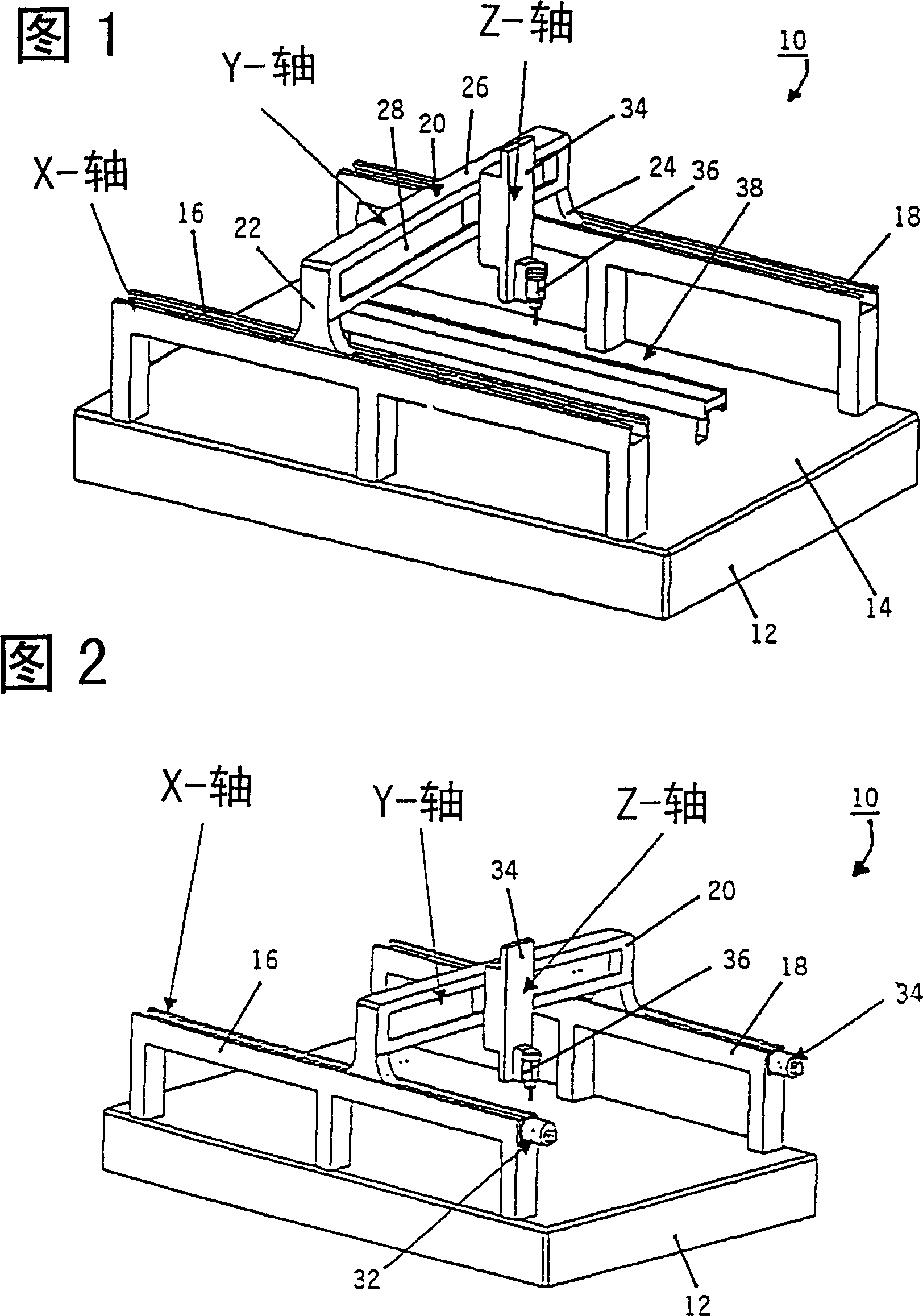
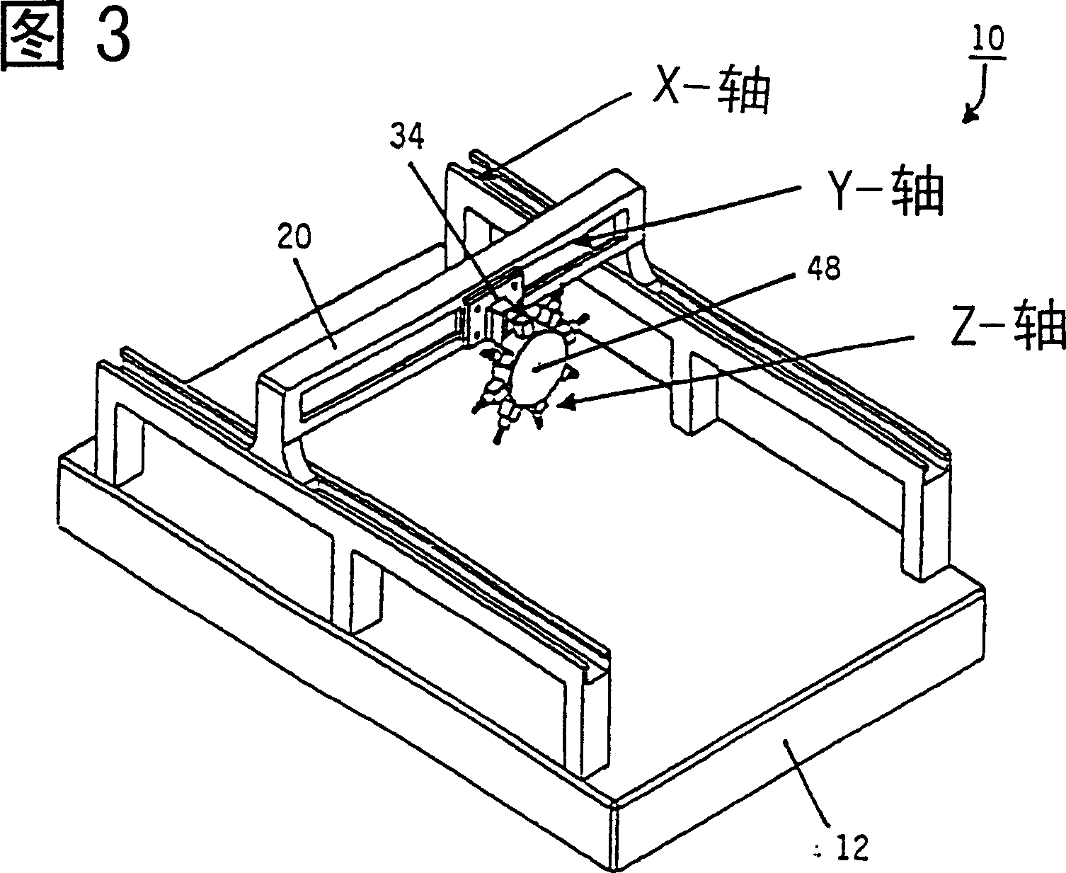
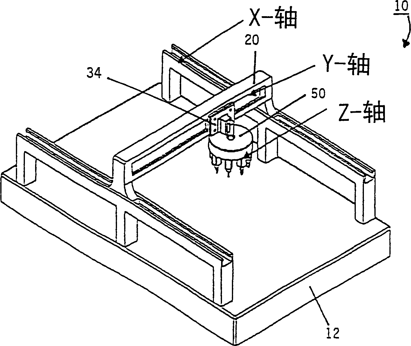
[0027] FIG. 1 shows a first exemplary embodiment of an assembly device 10 , which is used in particular as a fully automatic assembly device for the production of microsystems technology products and for carrying out assembly tasks in the semiconductor industry. Assembly device 10 has an assembly table 12 with an assembly surface or table top 14 . A conveyor system 16 , 18 is arranged on the table 14 . The conveyor system 16 , 18 consists of a rail system with two rails 16 , 18 arranged parallel to one another. It can also be seen that the guide rails 16 , 18 rest on the top of the assembly table 12 or on the top of the assembly table 14 . However, it is also possible to accommodate the conveyor systems 16 , 18 in the table top, that is to say on the assembly table, or to be articulated directly on the machine chassis in order to achieve an optimal introduction of forces into the supporting machine parts.

[0028] The gantry 20 is moved by means of the conveyor systems 16 , ...


PUM


Abstract

The invention relates to an assembly device (10), especially a fully automatic assembly device for producing microsystem technical products and for assembling components in the semiconductor industries. Said assembly device comprises an assembly table (12), at least one material transport system (38) that transports the products to be placed with components, and at least one transport system (16, 18, 54) that is mounted on the assembly table (12). The device is further provided with a component transport unit (34, 44, 64) that is mounted and displaced perpendicularly to the transport system (16, 18, 54) and that comprises at least one assembly head (36, 46, 66). Said component transport unit(s) (34, 44, 64) is / are mounted on one or more portals (20, 40, 60, 64). Said portals are displaced in parallel to the direction of transport of the products to be placed with components which products are in turn displaced by the material transport system(s) (38).

Description

technical field [0001] The invention relates to an assembly device, in particular a fully automatic assembly device for the production of microsystem technology products and assembly work in the semiconductor industry, comprising an assembly station, at least one material delivery system for the delivery of the parts to be assembled, At least one conveyor system arranged on the assembly table and at least one movable parts conveyor unit arranged perpendicular to the conveyor system and equipped with at least one assembly head. Background technique [0002] Such mounting devices are known from the prior art. Known types of assembly devices can be divided into three main categories: loaders for the production of electronic components, automatic assembly machines for the semiconductor industry, and laboratory devices for assembling models of microsystem technology demonstrators. However, these assembly devices have various disadvantages, especially for the production of micros...

Claims


Application Information

Patent Timeline
IPC IPC(8): H01L21/52H01L21/00H01L21/68H05K13/04
CPCY10T29/53178H05K13/0452Y10T29/49139H01L21/67144Y10T29/5313H01L21/68Y10T29/4913H05K13/0404H05K13/02
Inventor 约阿希姆·帕永克约尔格·波格特约亨·克拉尼希雅各布·菲舍尔
Owner SIEMENS ELECTRONICS ASSEMBLY SYST LLC
Learn More