
Method for making long period optical fibre grating

A fiber grating and manufacturing method technology, applied in the field of optical fiber communication and optical fiber sensing, can solve the problems of uneven angular distribution of optical fiber, bending deformation of LPFG, etc., and achieve the effects of eliminating physical deformation, reducing polarization-related loss, and being easy and controllable

Inactive Publication Date: 2004-12-22
DALIAN UNIV OF TECH
View PDF0 Cites 2 Cited by
  • Summary
  • Abstract
  • Description
  • Claims
  • Application Information

AI Technical Summary

Problems solved by technology

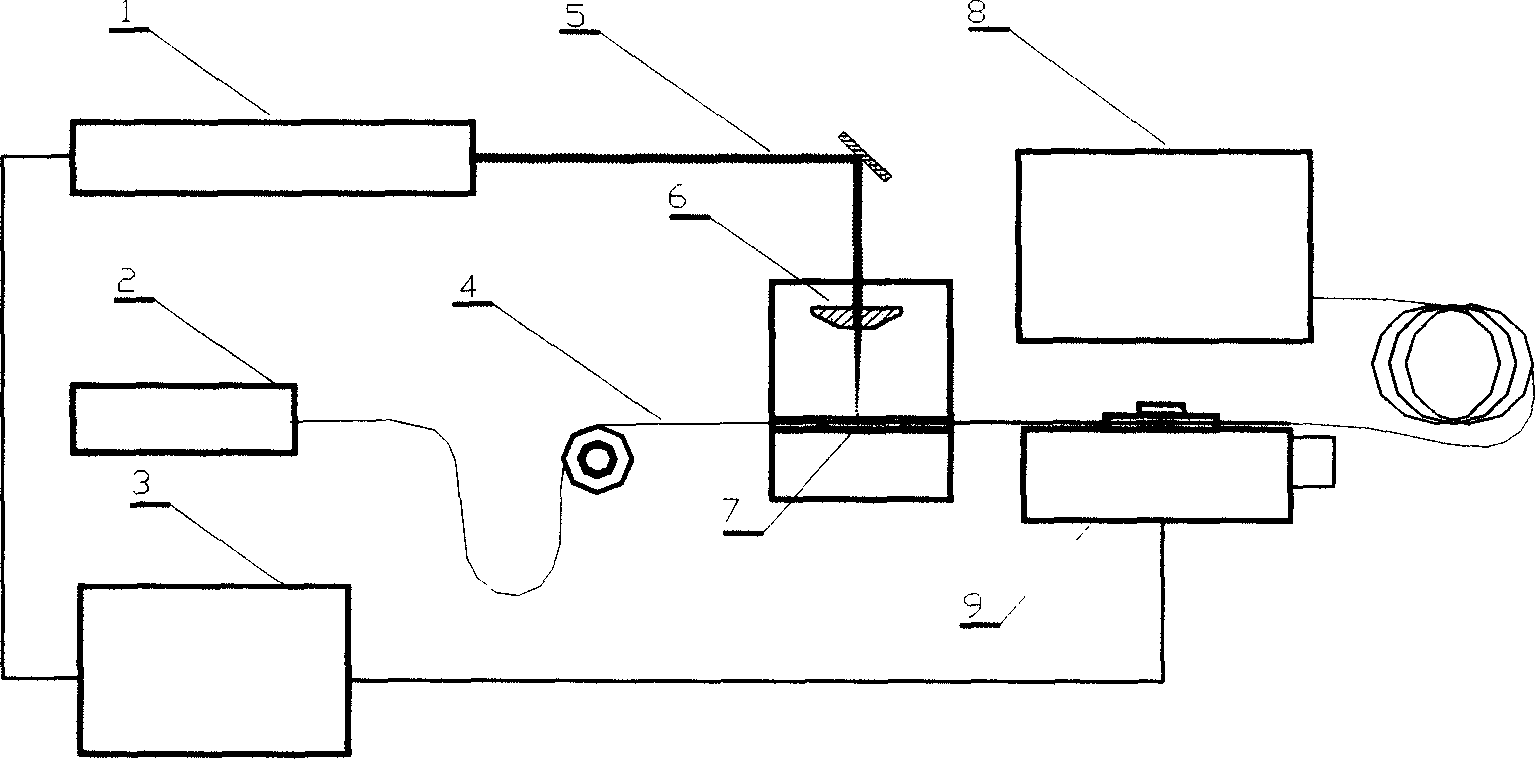
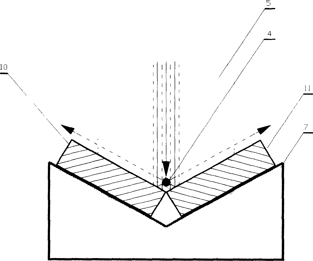
Due to CO 2 When the laser is single-sidedly written, the fiber is only irradiated on one side, and the other side is not irradiated by the laser, which causes the angular distribution of the refractive index change of the fiber to be uneven in the cross-section of the fiber, resulting in the resonant wavelength of the programmed LPFG being different from the The direction of bending has a strong dependence, and the written LPFG is prone to bending deformation

Method used


Image

  • Method for making long period optical fibre grating
  • Method for making long period optical fibre grating
  • Method for making long period optical fibre grating

Examples


Embodiment Construction

[0012] The best embodiment of the present invention will be described in detail below in conjunction with the accompanying drawings.

[0013] First according to CO 2 The operating characteristics of the laser are used to determine the parameters of the laser, such as operating frequency, duty cycle, and number of laser pulses. The frequency of the laser pulse used in the present invention is between 20k-24kHz, and the laser energy irradiated on the single-mode optical fiber (4) can be changed by adjusting the frequency and duty ratio of the laser pulse and the quantity of the laser pulse. Secondly, according to the resonant wavelength, peak loss, and bandwidth of the LPFG to be produced, determine the period of the LPFG and the length of the grating. The period number of the LPFG to be written can be calculated from the above two parameters, so that the electronically controlled translation stage (9) parameters are set. Place the bare fiber on the LPFG writing platform (7) e...


PUM


Abstract

The present invention belongs to the field of fiber communication and fiber sensor technology, and relates to the manufacture of passive optical device and fiber sensor. The present invention features that the long period fiber grating is made with 10.6 micron wavelength and 20-24 KHz frequency CO2 laser pulse and the three-beam focusing optical system comprising one cylindrical lens and two planar mirrors in 120 deg angle. Laser beam is focused symmetrically onto bare fiber, and computer controlled one-dimensional translating platform is shifted for alternate fiber shift and exposure to complete the making of the long period fiber grating. The said making process can improve the bending features of the long period fiber grating effectively and eliminating physical deformation of the fiber and is simple and flexible. The made long period fiber grating is used widely in filtering and gain smoothing in fiber communication and as wavelength demodulating fiber sensing element.

Description

technical field [0001] The invention belongs to the technical fields of optical fiber communication and optical fiber sensing. The invention relates to a manufacturing method of a long-period optical fiber grating and a corresponding device, and relates to the manufacturing technology of an optical passive device and an optical fiber sensor device in an optical fiber communication system. Background technique [0002] Since A.M.Vengsarkar and others successfully wrote long period fiber grating (Long Period Fiber Grating, hereinafter referred to as LPFG) in optical fiber in 1995, LPFG has been widely used in the field of optical fiber communication and optical fiber sensing technology, such as using LPFG without backward Reflection, small insertion loss and other advantages have been developed into fiber band-pass / rejection filters, EDFA gain smoothers, etc.; in terms of optical fiber sensing, LPFG has higher sensitivity to temperature and strain than fiber Bragg gratings, ma...

Claims


Application Information

Patent Timeline
Patent Type & Authority Patents(China)
IPC IPC(8): G02B6/124
Inventor 于清旭宋世德
Owner DALIAN UNIV OF TECH
Learn More