Laminated coil parts and production thereof
A coil component, layered technology, applied in coil manufacturing, transformer/inductor components, inductor/transformer/magnet manufacturing, etc., can solve the problems of high conductor resistance, rising cost, complex manufacturing process, etc., and reduce conductor resistance. Effect
- Summary
- Abstract
- Description
- Claims
- Application Information
AI Technical Summary
Problems solved by technology
Method used
Image
Examples
Embodiment 1
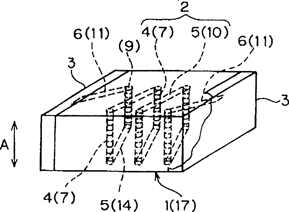
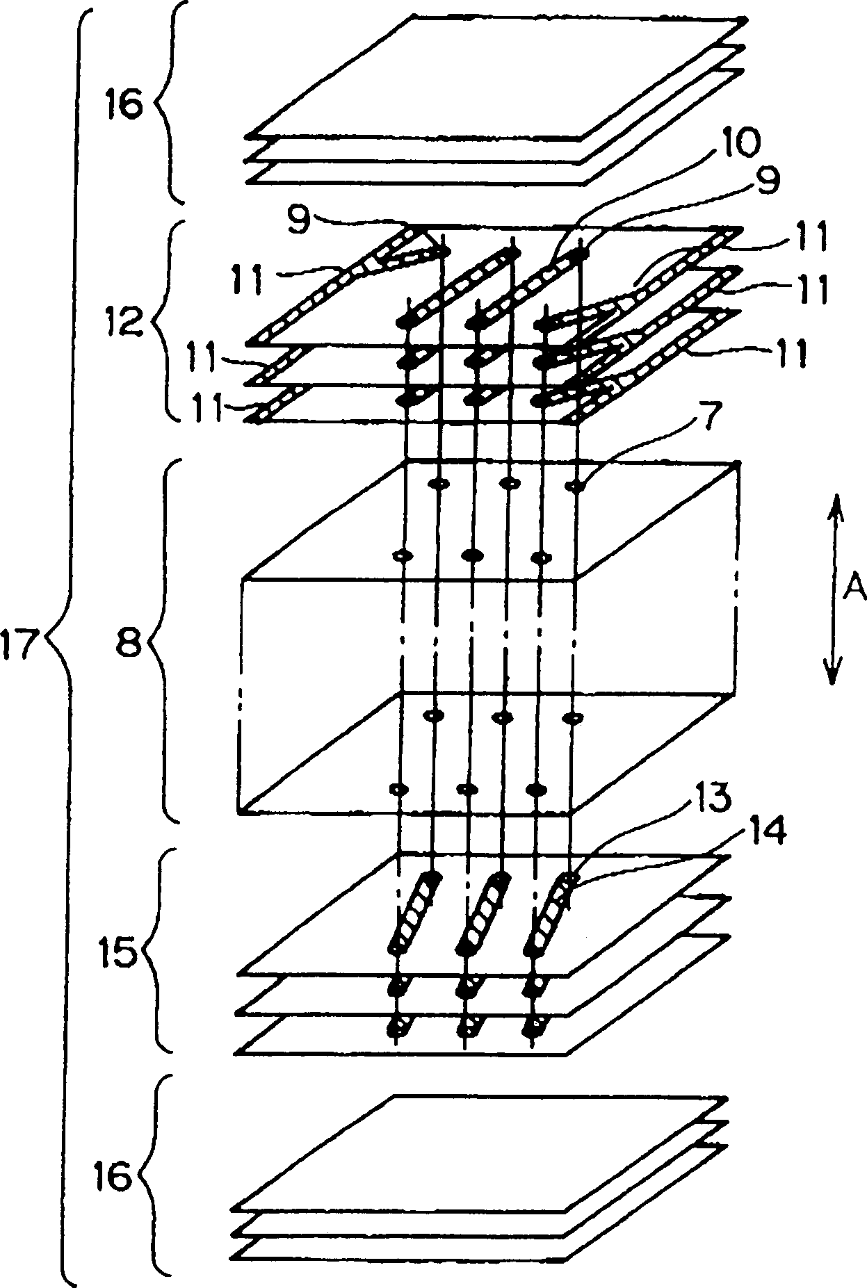
[0042] figure 1 It is a perspective view showing the appearance of a laminated inductor coil in one embodiment (Embodiment 1) of the present invention, figure 2 It is an exploded perspective view showing the laminate constituting the laminated inductor coil.
[0043] Such as figure 1 As shown, the structure of the laminated inductor coil in this embodiment 1 is: inside the element (laminated body) 1, a laminated coil 2 is provided around the central axis of the coil, so that the central axis is aligned with the stacking direction A of the element 1. Orthogonal; and, on both end faces of the element 1 , external electrodes 3 for input and output conducting to both ends of the coil 2 are provided.
[0044] Furthermore, inside the element 1, a plurality of through-holes 4 are provided at predetermined planar positions (positions viewed from the stacking direction) such that their axes are along the stacking direction A. As shown in FIG. In addition, in the inside of the ele...
Embodiment 2
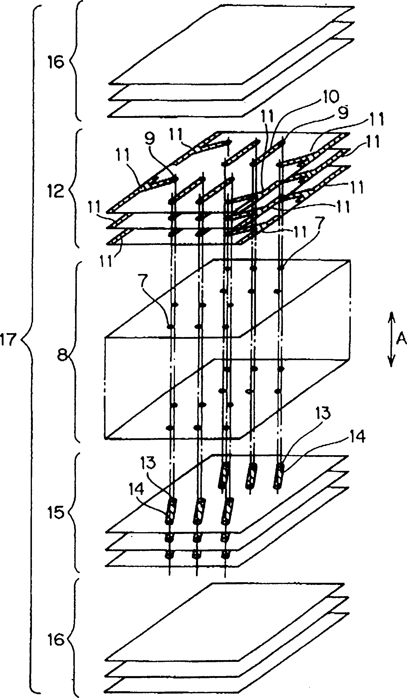
[0071] Figure 4 It is a perspective view showing the appearance of a laminated inductor coil in another embodiment (Embodiment 2) of the present invention, Figure 5 It is an exploded perspective view showing the laminate constituting the laminated inductor coil.
[0072] In the laminated inductor coil of the second embodiment, the lead-out electrode 6 of the multilayer structure is provided substantially in the center of the stacking direction A of the element 1 (laminated body), parallel to the stacking surface (orthogonal to the stacking direction A). direction).
[0073] In addition, other configurations including the overall configuration of the multilayer inductor coil of the second embodiment are the same as those of the multilayer inductor coil of the first embodiment described above, so descriptions thereof are omitted to avoid repetition. In addition, in Figure 4 and Figure 5 in, right with figure 1 and figure 2 The same symbols are used for the same or eq...
Embodiment 3
[0083] Figure 6 It is a perspective view showing the appearance of a laminated LC composite part in another example (Example 3) of the present invention.
[0084] In the laminated LC composite part of the present embodiment 3, a pair of external electrodes 40 for obtaining capacitance are provided opposite to the coil 2 (mainly the through hole 4), and the electrodes are formed from the central parts of the two side surfaces of the laminated body, that is, the element 1. , extended to the upper and lower sides.
[0085] That is, the multilayer LC composite part of the third embodiment is obtained by providing the external electrode 40 for obtaining capacitance on the element 1 constituting the multilayer inductor described in the first embodiment. The capacitance acquisition external electrode 40 is provided to face the through hole 4 which mainly constitutes the coil 2 .
[0086] In addition, similar to the external electrodes for input and output, the external electrodes ...
PUM
| Property | Measurement | Unit |
|---|---|---|
| thickness | aaaaa | aaaaa |
Abstract
Description
Claims
Application Information
 - Generate Ideas
- Intellectual Property
- Life Sciences
- Materials
- Tech Scout
- Unparalleled Data Quality
- Higher Quality Content
- 60% Fewer Hallucinations
Browse by: Latest US Patents, China's latest patents, Technical Efficacy Thesaurus, Application Domain, Technology Topic, Popular Technical Reports.
© 2025 PatSnap. All rights reserved.Legal|Privacy policy|Modern Slavery Act Transparency Statement|Sitemap|About US| Contact US: help@patsnap.com


