


Quick Research
Generate reliable direction feasibility study reports for your R&D in just a few steps.

Technical Q&A
Discover and master advanced knowledge NOW. Basics, ideas, possibilities, all at once.

Find Solutions
As an expert in R&D theories, this can generate solutions to your technical problems instantly.

Evaluate Feasibility
Analyze your overall solution with one click, know your potential R&D risks in advance.

Monitor Landscape
Get weekly tech updates, stay abreast of the latest tech innovations and key insights.
High dynamic range low ripple RSSI for zero-IF or low-IF receivers
A technology of received signal strength and indicator, applied in transmission monitoring, electrical components, transmission systems, etc., and can solve problems such as complex signals
- Summary
- Abstract
- Description
- Claims
- Application Information
AI Technical Summary
Problems solved by technology
Method used
Image

Examples
Embodiment Construction
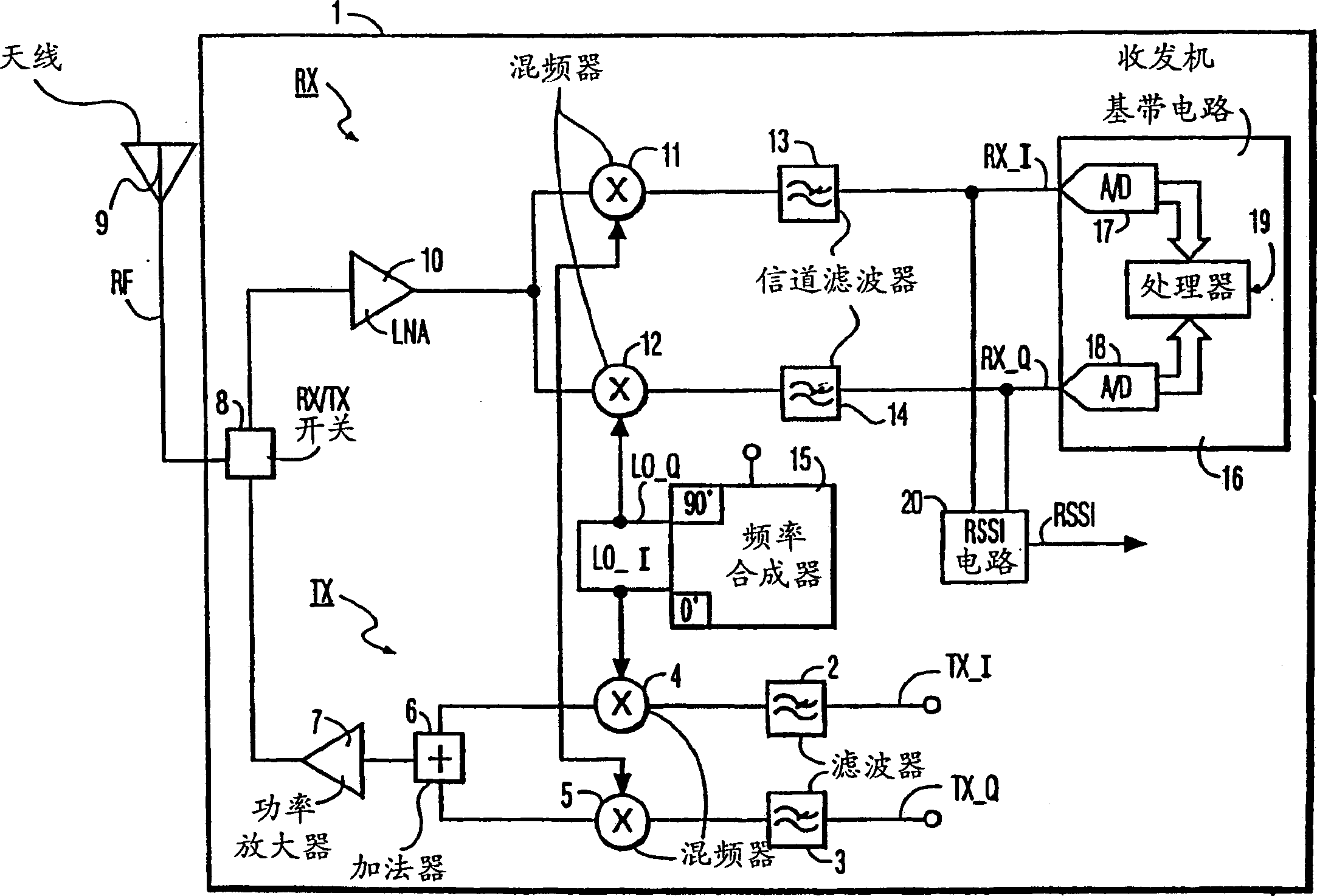
[0023] figure 1 A block diagram of a transceiver 1 is shown as a zero-IF or low-IF radio. Such a radio may be a time division duplex radio or any other suitable radio operating in the so-called 2.4 GHz ISM band according to the IEEE 802.11 standard. The transceiver 1 comprises a receiving branch RX and a transmitting branch T X . In another embodiment there is no transmission branch T X , the radio equipment is only a receiver. sending branch T X Includes a quadrature mixer with filters 2 and 3, mixers 4 and 5, and adder 6. Adder 6 is coupled to power amplifier 7 . The power amplifier 7 is coupled to R X / T X switch 8. R X / T X Switch 8 is coupled to antenna 9 . Orthogonal transmit signal T X -I and T X -Q is generated by a demodulator (not shown) and supplied to filters 2 and 3, respectively. receiving branch R X consists of a low noise radio frequency amplifier (LNA) 10 coupled to R X / T X switch. The LNA10 amplifies the radio frequency signal RF received ...
PUM
 Abstract
Description
Claims
Application Information
 - R&D Engineer
- R&D Manager
- IP Professional
- Industry Leading Data Capabilities
- Powerful AI technology
- Patent DNA Extraction
Browse by: Latest US Patents, China's latest patents, Technical Efficacy Thesaurus, Application Domain, Technology Topic, Popular Technical Reports.
© 2024 PatSnap. All rights reserved.Legal|Privacy policy|Modern Slavery Act Transparency Statement|Sitemap|About US| Contact US: help@patsnap.com