
Kettle type heat exchanger with fixed tube plate

A technology for fixing tube sheets and heat exchangers, applied to indirect heat exchangers, heat exchanger types, heat exchanger shells, etc., can solve problems such as difficult to guarantee welding quality, wear-through of heat exchange tube walls, and limited spacing , to achieve safe and reliable operation, prolong service life, and improve stress

Pending Publication Date: 2022-08-09
ANHUI WATERPOWER ENERGY SAVING TECH
View PDF1 Cites 0 Cited by
  • Summary
  • Abstract
  • Description
  • Claims
  • Application Information

AI Technical Summary

Problems solved by technology

The uneven stress of the tube bundle leads to the slight fluctuation of the operating conditions of the equipment, which can easily cause the resonance of the heat exchange tube. The resonance will inevitably lead to increased wear between the outer wall of the heat exchange tube and the tube hole of the support plate, and eventually lead to the deterioration of the heat exchange tube wall. wear through, causing leakage
[0003] Patent No. CN105180707A proposes a structure to improve the difference in the axial stiffness of the shell-side cylinder in the circumferential direction. Although it can be effectively improved, in the actual production and processing of the equipment, due to the limited spacing between adjacent longitudinal ribs, resulting in Welding between transverse ribs and longitudinal ribs, between longitudinal ribs and backing plates can be completed or the quality of welding is difficult to guarantee

Method used


Image

  • Kettle type heat exchanger with fixed tube plate
  • Kettle type heat exchanger with fixed tube plate
  • Kettle type heat exchanger with fixed tube plate

Examples


Embodiment 1

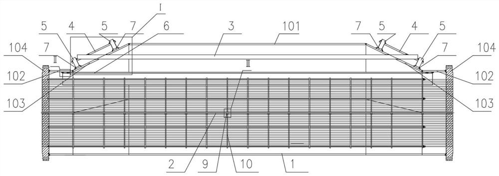
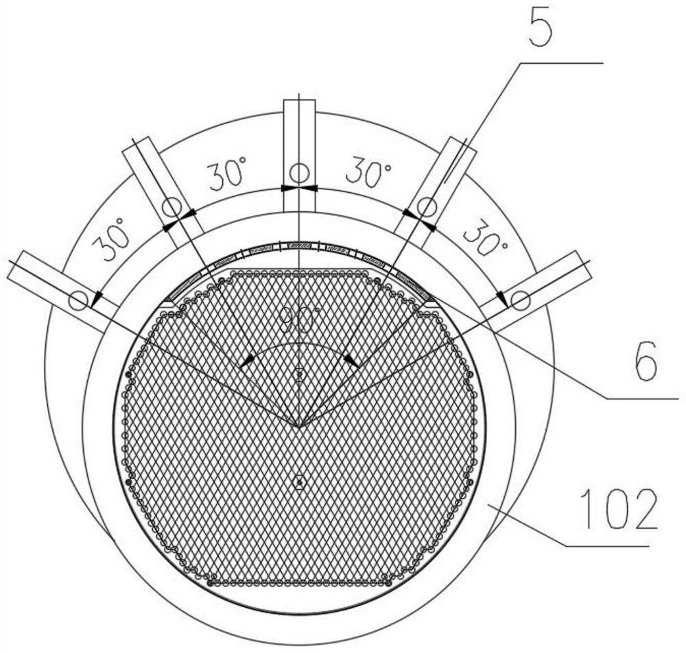
[0030] like Figure 1-6 As shown, a fixed tube sheet kettle type heat exchanger in this embodiment includes a shell side cylinder 1, tube sheets 104 located at both ends of the shell side cylinder 1, and heat exchange tubes 2 located inside the shell side cylinder 1, The shell-side cylinder 1 includes a large-diameter section cylinder 101 that is integrally connected and has a common bottom end, and a small-diameter section cylinder 102 located at both ends of the large-diameter section cylinder 101. The small-diameter section cylinder 102 and the large-diameter section cylinder 101 are eccentric. Cone 103 is connected.

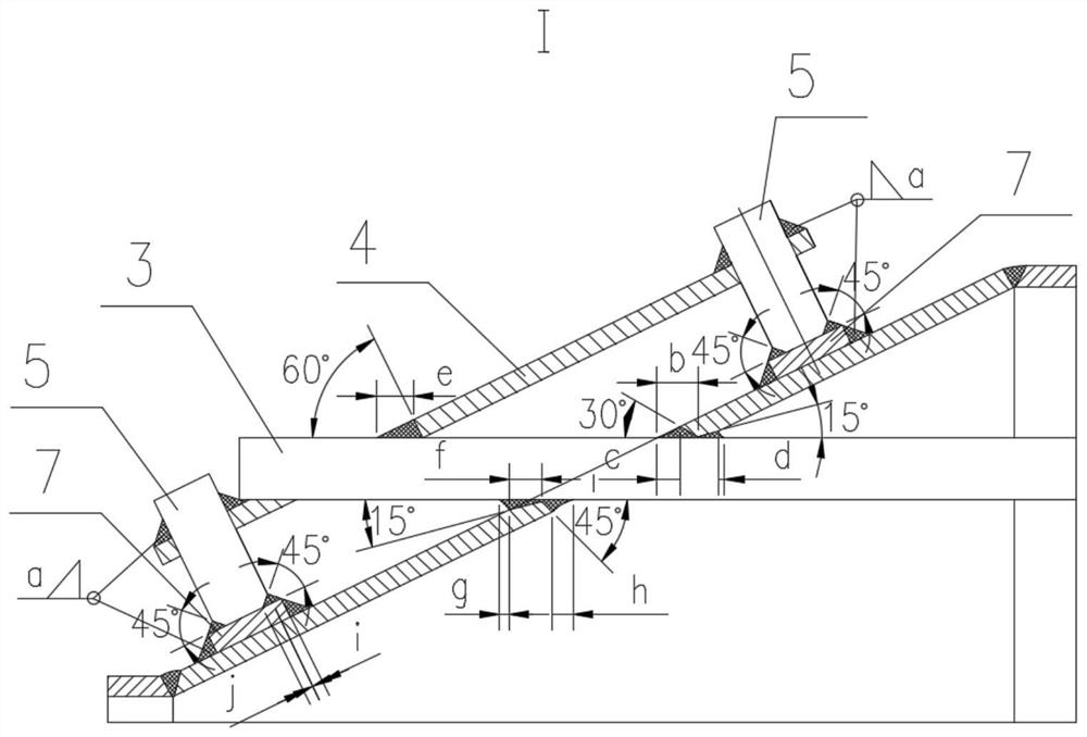
[0031] The two sets of eccentric cones 103 are connected by 6 tie rods 3, and the tie rod 3 and the eccentric cone 103 are fixed by double-sided welding, and the overhanging ends of the tie rod 3 are reinforced and fixedly connected, specifically the extension end sleeve of the tie rod 3 The two ends of the fixed plate 4 are welded and fixed with the reinfor...


PUM


Abstract

The invention relates to a kettle type heat exchanger with fixed tube plates, and belongs to the technical field of heat exchangers, the kettle type heat exchanger comprises a shell pass cylinder, tube plates located at the two ends of the shell pass cylinder and heat exchange tubes located in the shell pass cylinder, the shell pass cylinder comprises a large-diameter section cylinder and small-diameter section cylinders, the large-diameter section cylinder and the small-diameter section cylinders are integrally connected and share the bottom end, and the small-diameter section cylinders are located at the two ends of the large-diameter section cylinder. The small-diameter section cylinder body and the large-diameter section cylinder body are connected through eccentric cones, a pull rod is arranged between the eccentric cones at the two ends of the large-diameter section cylinder body, the two ends of the pull rod extend to the outer portions of the corresponding eccentric cones respectively, and fixing plates parallel to the inclined faces of the eccentric cones are arranged at the two ends of the pull rod respectively. The upper side and the lower side of the fixing plate are each provided with a plurality of reinforcing rods. The pull rods, the fixing plates, the reinforcing rods, the base plates and the eccentric cones form a barrel axial rigidity compensation structure, the barrel axial rigidity compensation structure and the arc-shaped reinforcing plates are in synergistic interaction, the pulling effect can be achieved, the stress of the tube plate and the tube bundle is obviously improved, and the stress tends to be evenly distributed.

Description

technical field [0001] The invention belongs to the technical field of heat exchangers, and in particular relates to a fixed tube sheet kettle type heat exchanger. Background technique [0002] Energy recovery and utilization is the main way to save energy, reduce emissions and green design. Therefore, kettle heat exchangers are widely used in absorption refrigeration, heat pumps and petrochemical production plants to recover energy, especially fixed tube sheet kettle heat exchangers. The shell of the fixed tube sheet kettle heat exchanger consists of a large diameter section, an eccentric cone and a small diameter section. The small diameter section is connected to the tube sheet, and the heat exchange tubes pass through the tube holes on the tube sheet, such as figure 1 shown. Due to the difference in axial stiffness in the circumferential direction, the stress distribution of tube sheets, tube bundles and shells is uneven, and this uneven stress distribution is particula...

Claims


Application Information

Patent Timeline
Patent Type & Authority Applications(China)
IPC IPC(8): F28D9/00F28F9/007F28F9/18
CPCF28D9/00F28F9/0075F28F9/18Y02P20/10
Inventor 蒋英明祝令辉郭盼盼
Owner ANHUI WATERPOWER ENERGY SAVING TECH
Learn More