
High-frequency long-service-life electromagnetic valve

A high-frequency, solenoid valve technology, applied in the field of solenoid valves, can solve problems such as cost increase and poor stability, and achieve the effects of cost reduction, flexibility improvement, and easy assembly and disassembly

Inactive Publication Date: 2022-08-09
迅耀机电(如皋)有限公司
View PDF0 Cites 0 Cited by
  • Summary
  • Abstract
  • Description
  • Claims
  • Application Information

AI Technical Summary

Problems solved by technology

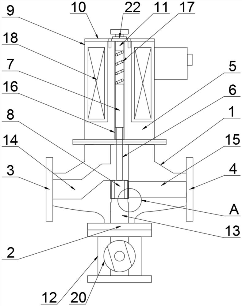
[0002] The traditional solenoid valve generally adopts a one-in-one-out structure. When it is necessary to control the opening and closing of two pipelines, only two solenoid valves can be installed in the two pipelines respectively, which increases the cost, and the existing solenoid valves are generally The valve plate or valve plate structure that adopts, stability is not good either, therefore, urgently needs a kind of improved technology to solve the above-mentioned problem existing in the prior art

Method used


Image

  • High-frequency long-service-life electromagnetic valve
  • High-frequency long-service-life electromagnetic valve
  • High-frequency long-service-life electromagnetic valve

Examples


Embodiment Construction

[0020] The technical solutions of the present invention will be clearly and completely described below with reference to the embodiments of the present invention and the accompanying drawings. Obviously, the described embodiments are only a part of the embodiments of the present invention, not all of the embodiments. Based on the embodiments of the present invention, all other embodiments obtained by those of ordinary skill in the art without creative work fall within the protection scope of the present invention;

[0021] It should be noted that, in the description of the present invention, it should be noted that the terms "inner", "outer", "upper", "lower", "both sides", "one end", "the other end" and "left" The orientation or positional relationship indicated by "right" and the like is based on the orientation or positional relationship shown in the drawings, and is only for the convenience of describing the present invention and simplifying the description, rather than ind...


PUM


Abstract

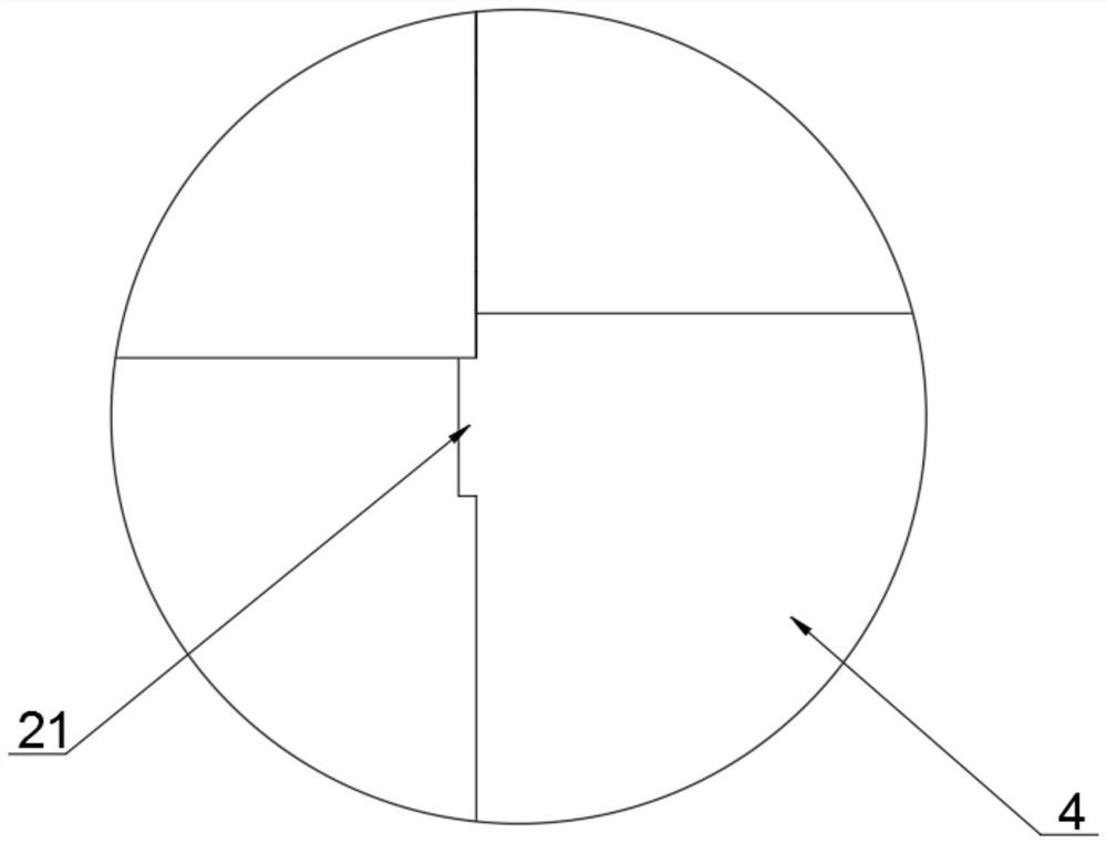
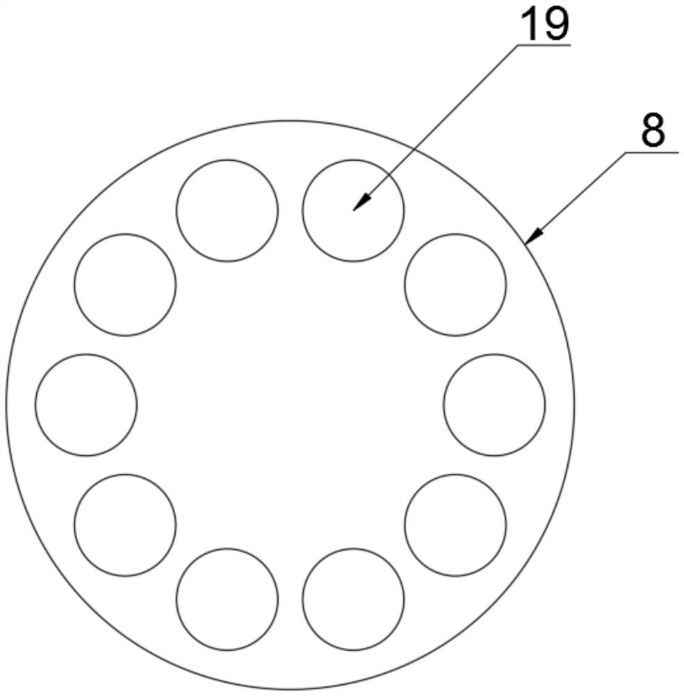
A first water outlet and a second water outlet are formed in the two ends of a valve seat, a water inlet is formed in the bottom end of the valve seat, a water inlet channel is formed in the water inlet, a first water outlet channel is formed in the first water outlet, and a second water outlet channel is formed in the second water outlet. The upper surface of the valve seat is connected with the valve body, a sliding sleeve is arranged in the valve body, an iron core is arranged at the top end of the valve rod and movably arranged in the sliding sleeve, the valve body is sleeved with a coil box, an electromagnetic coil is arranged in the coil box, and a valve column is arranged at the bottom end of the valve rod. The valve rod is movably arranged in the water inlet channel, the side wall of the valve rod is matched with the first water outlet channel and the second water outlet channel, and the water inlet is connected with a switch valve piece through a flange. The structure is reasonable, liquid drainage of the water outlet channels is controlled and switched through the valve rod, flow division control is achieved, the cost is greatly reduced, the sealing performance is better, and the compression resistance is higher.

Description

technical field [0001] The invention relates to the technical field of solenoid valves, in particular to a high-frequency and long-life solenoid valve. Background technique [0002] The traditional solenoid valve generally adopts a one-in-one-out structure. When it is necessary to control the opening and closing of two pipelines, only two solenoid valves can be installed in the two pipelines respectively, which increases the cost, and the existing solenoid valves are commonly used. The adopted valve plate or valve plate structure has poor stability. Therefore, an improved technology is urgently needed to solve the above problems existing in the prior art. SUMMARY OF THE INVENTION [0003] The purpose of the present invention is to provide a high-frequency and long-life solenoid valve, which is provided with one water inlet and two water outlets. A set of pipelines can use only one solenoid valve, the cost is greatly reduced, and the flexibility is greatly improved. The va...

Claims


Application Information

Patent Timeline
Patent Type & Authority Applications(China)
IPC IPC(8): F16K31/06
CPCF16K31/0603F16K31/0675
Inventor 沈杰李晓娜
Owner 迅耀机电(如皋)有限公司
Learn More