Tunnel ventilation opening structure

A technology for tunnel ventilation and vents, which is applied in mine/tunnel ventilation, tunnel, tunnel lining, etc. It can solve problems such as unfavorable structural stress, high requirements for tunnel surrounding rock conditions, inconvenient maintenance, transportation and maintenance, etc. Rock stability and structural stress, mature construction technology and methods, and convenient operation and maintenance management

Pending Publication Date: 2022-08-05
CCCC SECOND HIGHWAY CONSULTANTS CO LTD
View PDF0 Cites 0 Cited by
  • Summary
  • Abstract
  • Description
  • Claims
  • Application Information

AI Technical Summary

Problems solved by technology

[0005] (2) High construction risk and low structural safety
Due to multiple excavation interference, it is easy to cause cracking and instability of the excavated support structure; there are many straight wall structures at the intersection, which is not conducive to the structural force, and the structural safety is low
[0006] (3) It is not conducive to the excavation of the auxiliary main hole
The traditional "upward expansion" scheme has a large height difference between the connecting channel and the road surface of the main cave, making it difficult for construction vehicles to freely enter and exit the main cave, making it difficult to serve as an auxiliary construction channel for the main cave
[0007] (4) Overhaul and maintenance during the operation period need to climb straight ladders, which is inconvenient for overhaul and transportation of maintenance materials
[0008] (5) Poor formation applicability
The traditional "upward expansion" scheme has many straight wall structures and is large in height. If the excavation support is not timely, it will easily cause the instability of the surrounding rock. It has high requirements on the surrounding rock conditions of the tunnel. When the rock is grade Ⅳ or Ⅴ soft rock, the construction risk is extremely high

Method used


Image

  • Tunnel ventilation opening structure
  • Tunnel ventilation opening structure
  • Tunnel ventilation opening structure

Examples


Embodiment Construction

[0039] The present invention will be described in detail below with reference to specific embodiments. The following examples will help those skilled in the art to further understand the present invention, but do not limit the present invention in any form. It should be noted that, for those skilled in the art, several modifications and improvements can be made without departing from the concept of the present invention. These all belong to the protection scope of the present invention.

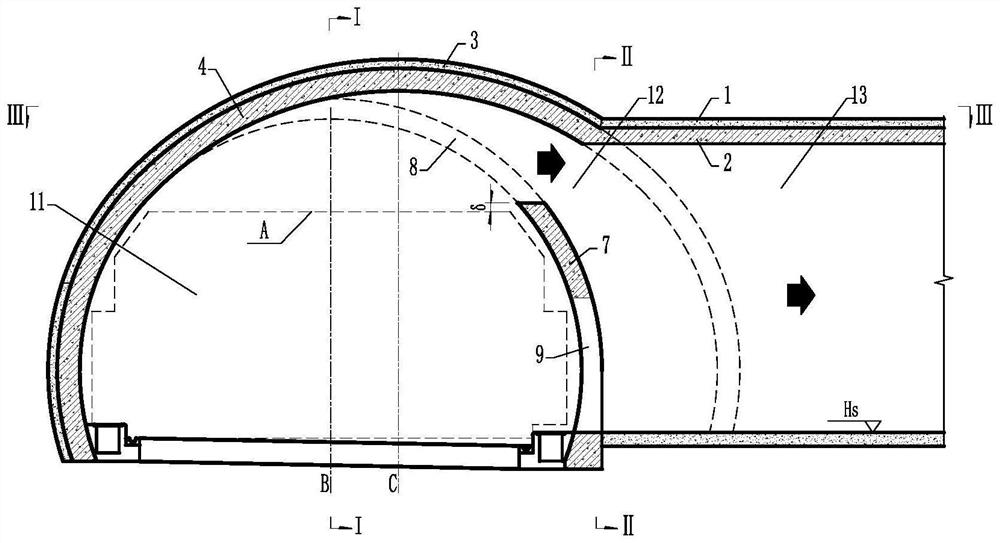
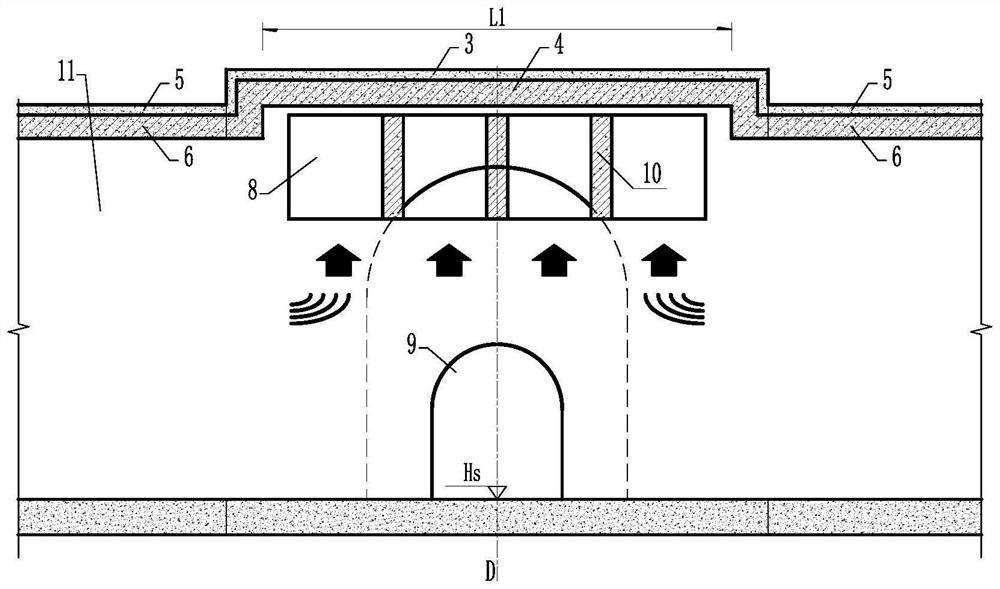
[0040] In order to solve the shortcomings of the traditional vent type, an embodiment of the present invention provides a tunnel vent structure, and the tunnel vent structure has a tunnel vent cross-connection type, refer to Figure 1-8 As shown, the structure of the tunnel vent includes: the main tunnel 11, which is used for the normal passage of vehicles and the arrangement of auxiliary facilities; the communication channel 13, which is used for connecting the main tunnel 11 and the ventil...


PUM


Abstract

The invention provides a tunnel ventilation opening structure which comprises a tunnel main hole used for normal passing of vehicles and arrangement of ancillary facilities. The connection channel is used for communicating the tunnel main hole with the ventilation shaft; the widened belt is used for converting air flow and facilitating turning of construction vehicles, the widened belt and the connection channel are arranged on the same side, the connection channel intersects with the outline of the widened belt, a ventilation window is formed in the arch portion of the tunnel main hole at the intersection position of the connection channel and the axis of the connection channel, and the ventilation window is communicated with the ventilation window. And the inner contour of the broadband is the same as that of the tunnel emergency parking strip. The tunnel ventilation opening structure is simple in structure, reasonable in stress, simple, practical, convenient to construct, high in safety, convenient to operate, maintain and manage, and capable of effectively achieving coordination and consideration of tunnel ventilation, construction and operation management.

Description

technical field [0001] The invention relates to the technical field of tunnel engineering, in particular, to a tunnel vent structure. Background technique [0002] With the rapid development of highways, railways and urban underground roads in my country, more and more long tunnels are being built. When the length of the tunnel exceeds a certain scale, it is usually necessary to set up vertical and inclined shafts to assist the ventilation of the main tunnel to dilute the smoke, carbon monoxide and odor in the air. The vertical and inclined shafts are connected with the main tunnel through a communication channel. Due to the large scale of the tunnel and the tight construction period, the vertical and inclined shafts (especially the inclined shafts) usually double as construction channels to assist the excavation of the main tunnel. Therefore, the structural type of the vent at the intersection of the communication channel and the main hole is not only related to the ventil...

Claims


Application Information

Patent Timeline
Patent Type & Authority Applications(China)
IPC IPC(8): E21D9/14E21D11/10E21F1/00
CPCE21D9/14E21D11/10E21D11/105E21D11/102E21F1/003Y02A30/60
Inventor 毛红飞程勇李昕李华魏龙海蔡厚强李波崔庆龙
Owner CCCC SECOND HIGHWAY CONSULTANTS CO LTD
Why Eureka
Try Eureka