
Double faced adhesive tape punching system

A double-sided tape, punching machine technology, applied in thin material handling, climate sustainability, final product manufacturing, etc., can solve problems such as low production efficiency and inconvenient operation, reduce manpower dependence, and improve stability. , the effect of improving the convenience of operation

Pending Publication Date: 2022-08-05
李跃泉
View PDF0 Cites 0 Cited by
  • Summary
  • Abstract
  • Description
  • Claims
  • Application Information

AI Technical Summary

Problems solved by technology

In the production of double-sided adhesive tape, the production system usually uses a flat die-cutting machine. Compared with other die-cutting equipment, the flat die-cutting machine has a simple structure, easy to replace the punching and indentation plate, and is suitable for materials of different grammes. There are a series of advantages such as precise punching, but its shortcomings are also obvious. In small factories that undertake production orders for different raw materials, in order to prevent the double-sided adhesive material from shaking during the production process and affect the processing quality, it is usually equipped with multiple Feeding shafts with different diameters are used to adapt to materials with different inner diameters. Therefore, when changing double-sided adhesive materials with different diameters, the feeding shafts must be replaced according to requirements, which is inconvenient to operate and low in production efficiency.

Method used


Image

  • Double faced adhesive tape punching system
  • Double faced adhesive tape punching system
  • Double faced adhesive tape punching system

Examples


Embodiment approach

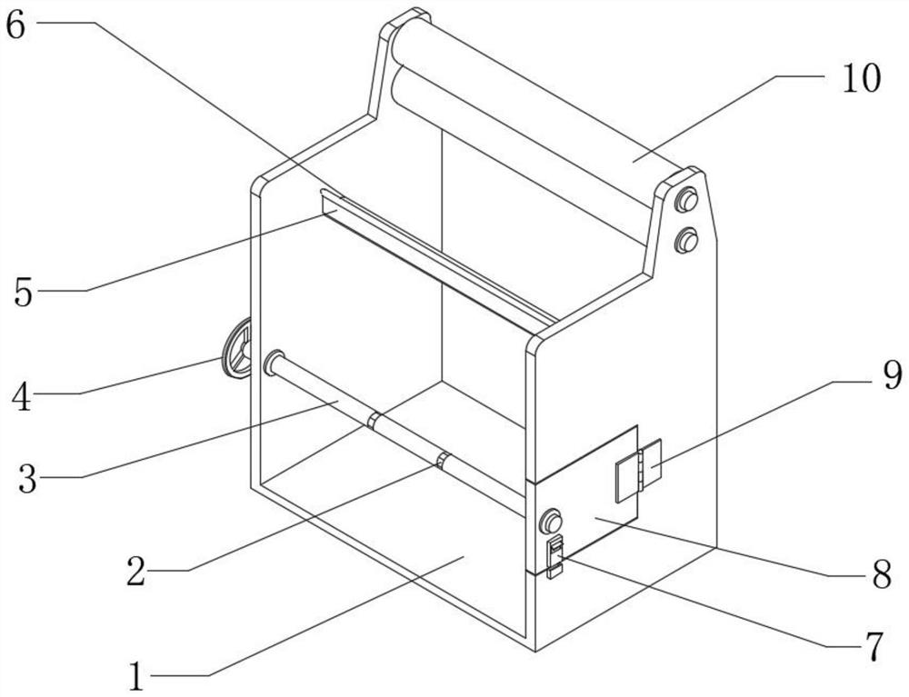
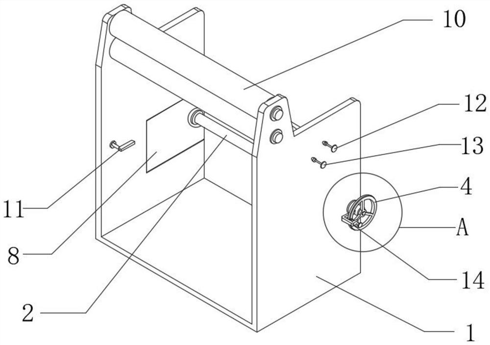
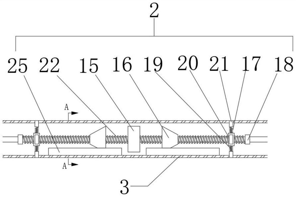
[0054] As an embodiment of the present invention, refer to figure 1 , image 3 and Image 6 , the feeding shaft 3 is provided with a built-in cavity, and the raw material fixing device 2 includes:

[0055] The screw 22, the screw 22 is fixedly installed on the feeding shaft 3, and the screw 22 passes through the built-in cavity;

[0056] The sliding table 25, two sliding tables 25 are symmetrically installed on the inner side wall of the feeding shaft 3, and the two sliding tables 25 are both provided with sliding grooves;

[0057] The round table 16 and the screw 22 are connected with two round tables 16 by a symmetrical screw drive, and the two round tables 16 are both provided with protruding blocks that cooperate with the chute on the sliding table 25;

[0058]The first limit block 15, the first limit block 15 is fixedly installed on the screw 22, and is located in the middle of the two circular platforms 16;

[0059] For the second limit block 18, two second limit blo...


PUM


Abstract

The invention relates to the technical field of punching, in particular to a double faced adhesive tape punching system which comprises a fixing frame, two pressing rollers are fixedly installed on the inner side wall of the fixing frame, a feeding shaft is fixedly installed on the inner side wall of the fixing frame, and a punching machine is fixedly installed on the fixing frame. A discharging device is fixedly installed on the side, away from the fixing frame, of the punching machine, a raw material fixing device is fixedly installed on the feeding shaft, and a movable door matched with the feeding shaft is rotationally installed on the fixing frame. According to the feeding device, the raw material fixing device on the feeding shaft shrinks and expands to adapt to raw materials with different inner diameters, and the raw material fixing device and the movable door are operated to facilitate sleeving and disengaging of the raw materials in the feeding process; and the situation that the punching precision is reduced due to the fact that the feeding shaft and the double-faced adhesive tape raw materials rotate or slide relatively in the production process is avoided.

Description

technical field [0001] The invention relates to the technical field of punching, in particular to a double-sided adhesive punching system. Background technique [0002] The double-sided tape punching system is mainly used to realize the one-time completion of the double-sided tape from feeding, die-cutting to waste discharge, etc. It usually consists of a feeding part, a molding part, and a discharging part. In the production of double-sided tape, the production system usually uses a flat die-cutting machine. Compared with other die-cutting equipment, the flat-bed die-cutting machine has a simple structure, easy to replace the punching and indentation plate, suitable for materials of different weights, There are a series of advantages such as accurate punching, but its shortcomings are also obvious. In small factories that undertake production orders for different raw materials, in order to prevent the double-sided adhesive material from shaking during the production process...

Claims


Application Information

Patent Timeline
IPC IPC(8): B65H19/12B65H16/02B65H16/06
CPCB65H19/126B65H16/02B65H16/06Y02P70/50
Inventor 李跃泉王明丽
Owner 李跃泉
Learn More