


Quick Research
Generate reliable direction feasibility study reports for your R&D in just a few steps.

Technical Q&A
Discover and master advanced knowledge NOW. Basics, ideas, possibilities, all at once.

Find Solutions
As an expert in R&D theories, this can generate solutions to your technical problems instantly.

Evaluate Feasibility
Analyze your overall solution with one click, know your potential R&D risks in advance.

Monitor Landscape
Get weekly tech updates, stay abreast of the latest tech innovations and key insights.
Method for assembling winding drum and winding drum shaft of large ship lift
An assembly method and reel shaft technology, which are applied in the direction of hoisting device, spring mechanism, metal processing equipment, etc., can solve the problems of the accuracy and reliability of the reel shaft, the safety risk of hoisting and turning over, and shorten the movement time. Distance and operation time, reduce construction cost, solve the effect of horizontal displacement
- Summary
- Abstract
- Description
- Claims
- Application Information
AI Technical Summary
Problems solved by technology
Method used
Image

Examples
Embodiment 1
[0041] As a basic embodiment of the present invention, the present invention includes a method for assembling a reel and a reel shaft of a large ship lift, comprising the following steps:
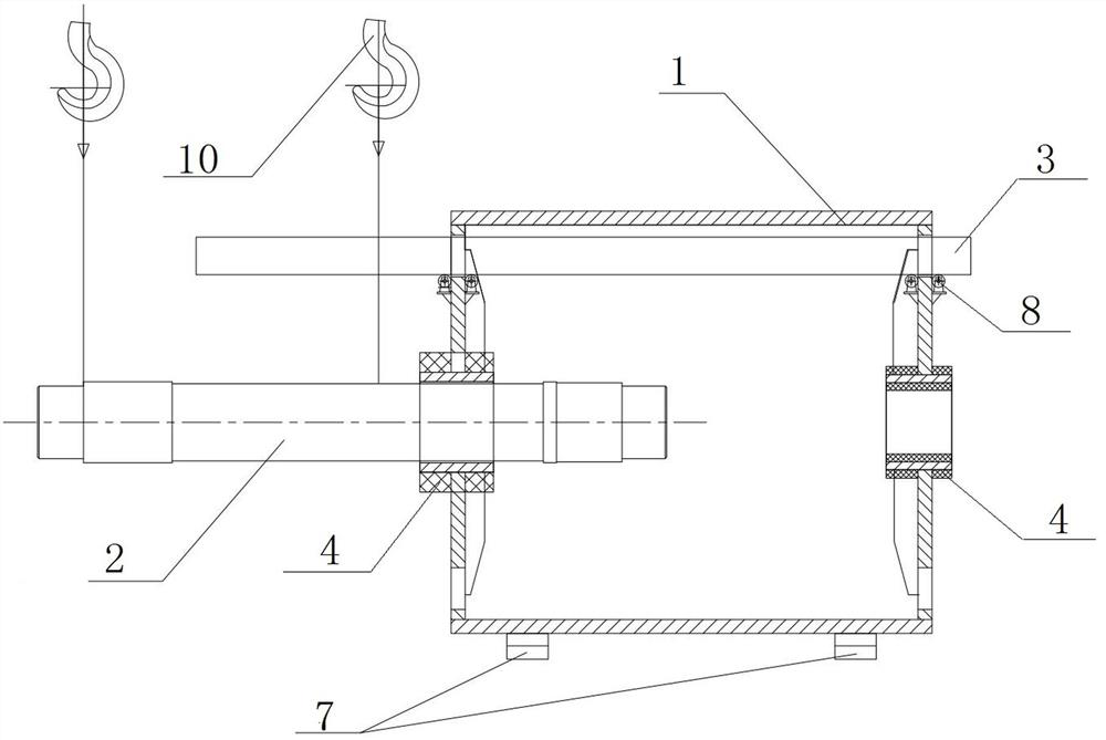
[0042] S 1 . The reel 1 is positioned horizontally; along the assembly direction of the reel shaft 2, the reel 1 includes an input end and an output end.
[0043] S 2 . Assemble the horizontal displacement hanging beam 3 inside the drum 1, and install two sets of heating devices 4.
[0044] S 3 . The first stage assembly of the reel shaft 2: use the external force to push the reel shaft 2 from the input end of the reel 1 into the inside of the reel 1, so that the end of the reel shaft 2 is close to the inner hole of the reel at the output end, even if the reel shaft 2 Most of the spools are assembled inside the reel 1, and the adjustment makes the reel shaft 2 and the center of the inner hole of the reel the same.
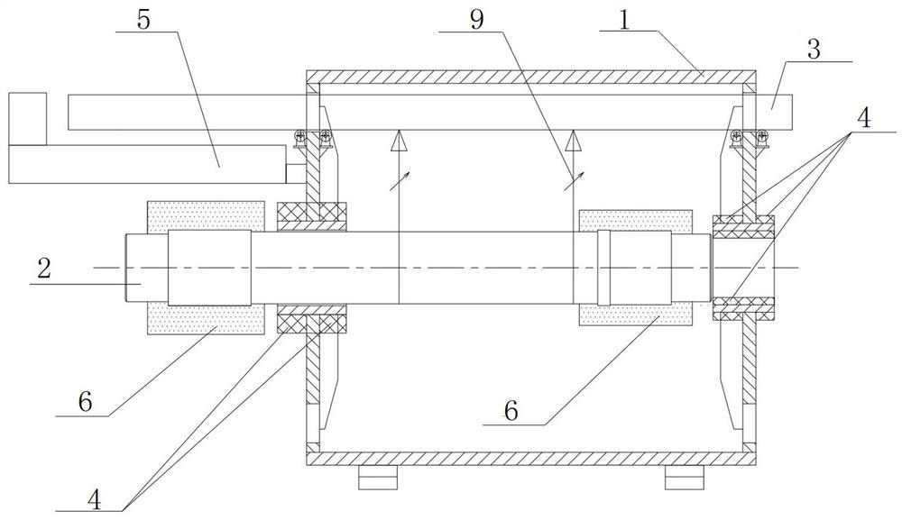
[0045] S 4 . Install the cooling device 6 on the two mating sections o...
Embodiment 2
[0049] As the best embodiment of the present invention, the present invention includes a method for assembling a reel and a reel shaft of a large ship lift, comprising the following steps:
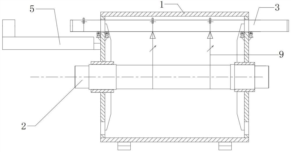
[0050] S 1 . With reel 1 in place horizontally, fix reel 1 on tool support 7 that prevents reel 1 from rotating. Refer to the manual attached Figure 4 , On the webs at both ends of the reel 1, the circular holes for blanking are arranged vertically, and the upper and lower holes pass through the axis line. Along the assembly direction of the reel shaft 2, the reel 1 includes an input end and an output end, the reel inner hole on the input end is a large hole, and the reel inner hole on the output end is a small hole.
[0051] S 2 . Assemble the horizontal displacement hanging beam 3 inside the drum 1, that is, after the drum 1 is fixed vertically and horizontally adjusted and aligned, install the movable horizontal displacement hanging beam 3, and the horizontal displacement hanging be...
PUM
| Property | Measurement | Unit |
|---|---|---|
| length | aaaaa | aaaaa |
Abstract
Description
Claims
Application Information
 - R&D Engineer
- R&D Manager
- IP Professional
- Industry Leading Data Capabilities
- Powerful AI technology
- Patent DNA Extraction
Browse by: Latest US Patents, China's latest patents, Technical Efficacy Thesaurus, Application Domain, Technology Topic, Popular Technical Reports.
© 2024 PatSnap. All rights reserved.Legal|Privacy policy|Modern Slavery Act Transparency Statement|Sitemap|About US| Contact US: help@patsnap.com