
Cleaning system and method for ultrafiltration membrane

A cleaning system and ultrafiltration membrane technology, applied in ultrafiltration, chemical instruments and methods, membrane technology, etc., can solve the problems of reducing the water production time of membrane system, decline in filtration performance, membrane corrosion, etc., to reduce backwashing and chemical The effect of cleaning frequency, reducing the content of organic matter in the effluent, and improving the overall online rate

Pending Publication Date: 2022-08-05
北京北排膜科技有限公司
View PDF7 Cites 0 Cited by
  • Summary
  • Abstract
  • Description
  • Claims
  • Application Information

AI Technical Summary

Problems solved by technology

NIPS membrane has disadvantages such as relatively poor chemical stability and low mechanical strength, while TIPS membrane has a certain improvement in mechanical strength compared with NIPS membrane, but still has the problems of relatively poor chemical stability and hydrophilicity.
The above factors make the PVDF membrane prone to degradation of filtration performance or broken wires caused by membrane corrosion under conventional membrane cleaning methods, resulting in a reduction in the overall service life of the membrane.
[0006] (2) Incomplete cleaning: Whether it is physical cleaning or chemical cleaning, in essence, after the membrane pollution reaches a certain level, restorative cleaning is performed, and as the service life increases, the water production performance of the ultrafiltration membrane will decrease year by year. This also shows that conventional physical or chemical cleaning cannot completely remove the contamination of the membrane, and there are cases where the cleaning is not thorough
[0007] (3) Cleaning leads to low online rate of ultrafiltration membrane operation: during the operation of the ultrafiltration system, after a period of continuous water production, backwashing or chemical cleaning is required to ensure that the water flux of the membrane is maintained within the design range, while Frequent backwashing or chemical cleaning will reduce the water production time of the membrane system and reduce the overall online rate of the membrane system
[0008] Therefore, in view of the problems of incomplete cleaning, affecting the online rate of membrane operation, and even reducing the life of the membrane in the current ultrafiltration membrane cleaning technology, it is urgent to propose a new system and method for ultrafiltration membrane cleaning.

Method used


Image

  • Cleaning system and method for ultrafiltration membrane
  • Cleaning system and method for ultrafiltration membrane
  • Cleaning system and method for ultrafiltration membrane

Examples


Embodiment 1

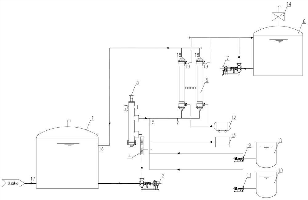
[0051] This embodiment provides a cleaning system for an ultrafiltration membrane, such as figure 1 As shown, the system includes a raw water tank 1, an ultrafiltration inlet pump 2, a self-cleaning filter 3, an ultrafiltration device 5, a water production tank 6, an exhaust gas destruction device 14, a backwash water pump 7, an air compressor subsystem 12, and an ozone generator. Subsystem and dosing and cleaning subsystem;

[0052] The ozone generator subsystem includes a mixer 4 and an ozone generator 13;

[0053] The water outlet of the raw water tank 1, the ultrafiltration water inlet pump 2, the mixer 4, the self-cleaning filter 3, the ultrafiltration equipment 5 and the water inlet of the water production tank 6 are connected in sequence; The top of the water tank 6 is used to recover the ozone entering the water production tank 6;

[0054] The ozone generator 13 communicates with the mixer 4;

[0055] The top product water outlet 19 of the ultrafiltration device 5 i...

Embodiment 2

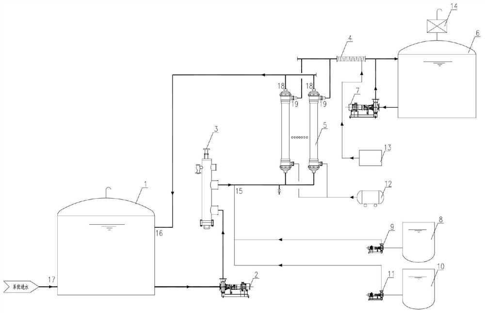
[0060] This embodiment provides a cleaning system for an ultrafiltration membrane, such as figure 2 As shown, the system includes a raw water tank 1, an ultrafiltration inlet pump 2, a self-cleaning filter 3, an ultrafiltration device 5, a water production tank 6, an exhaust gas destruction device 14, a backwash water pump 7, an air compressor subsystem 12, and an ozone generator. Subsystem and dosing and cleaning subsystem;

[0061] The water outlet of the raw water tank 1, the ultrafiltration water inlet pump 2, the self-cleaning filter 3, the ultrafiltration equipment 5 and the water inlet of the water production tank 6 are connected in turn; the exhaust gas destruction device 14 is arranged on the top of the water production tank 6 , for recovering the ozone entering into the water production tank 6;

[0062] The top product water outlet 19 of the ultrafiltration device 5 is also communicated with the product water outlet of the water product tank 6 through the backwash ...

Embodiment 3

[0068] The present embodiment provides a cleaning method for an ultrafiltration membrane. The method adopts the system described in Embodiment 1 and includes the following steps:

[0069] S1: When the liquid level meter detects that the liquid level in the raw water tank 1 reaches the starting liquid level, the ultrafiltration feed pump 2 is automatically turned on, and the raw water in the raw water tank 1 and the ozone from the ozone generator 13 are transported to the The mixer 4 and the self-cleaning filter 3 preliminarily filter out the impurities of larger particles in the water, and through the self-cleaning filter 3 and the mixer 4, the ozone is fully contacted with the organic pollutants in the raw water, and an oxidation reaction occurs. , to completely decompose organic pollutants;

[0070] The dosage of the ozone is 10 mg / L;

[0071] S2: After the raw water that has undergone the oxidative decomposition is sent to the ultrafiltration equipment 5 for filtration, it...


PUM


Abstract

The invention belongs to the technical field of ultrafiltration membrane cleaning, and discloses an ultrafiltration membrane cleaning system and method. The system comprises a raw water tank, an ultrafiltration water inlet pump, a self-cleaning filter, ultrafiltration equipment, a water producing tank, a tail gas destroying device, a backwashing water pump, an air compressor subsystem, an ozone generator subsystem and an optional dosing cleaning subsystem. By using the novel ultrafiltration membrane system in cooperation with the ozone pre-oxidation method, the service life of the ultrafiltration membrane can be prolonged, the cleaning effect is improved, and the influence on the online rate of membrane operation is reduced.

Description

technical field [0001] The invention belongs to the technical field of ultrafiltration membrane cleaning, and more particularly, relates to a cleaning system and method for an ultrafiltration membrane. Background technique [0002] Membrane fouling refers to the reduction of membrane pore size due to the adsorption and deposition of particles, colloidal particles or solute macromolecules in water and the membrane due to physical and chemical interaction or mechanical action during the membrane filtration process on the membrane surface or in the membrane pores. Blockage causes irreversible changes in the permeate flow and separation characteristics of the membrane. In the field of water treatment, ultrafiltration membranes are inevitably polluted during normal operation, which is also an insurmountable problem that restricts the normal water production of membranes. [0003] At present, the common methods for the prevention and control of membrane fouling are physical clean...

Claims


Application Information

Patent Timeline
Patent Type & Authority Applications(China)
IPC IPC(8): B01D65/02B01D61/14C02F9/04
CPCB01D65/02B01D61/145C02F9/00C02F1/001C02F1/444C02F1/78
Inventor 刘江艾冰卢圣其雍文彬
Owner 北京北排膜科技有限公司
Learn More