Auxiliary chair for pediatric blood drawing
A pediatric, slider technology, used in dental chairs, applications, dentistry, etc., can solve the problems of inability to handle heating of hands, children's tampering, etc., to achieve convenient blood drawing operations, improve comfort, and smooth blood drawing operations. Effect
- Summary
- Abstract
- Description
- Claims
- Application Information
AI Technical Summary
Problems solved by technology
Method used
Image
Examples
Embodiment 1
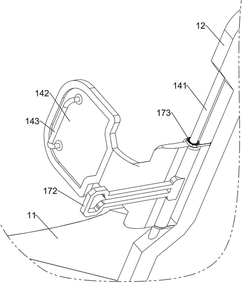
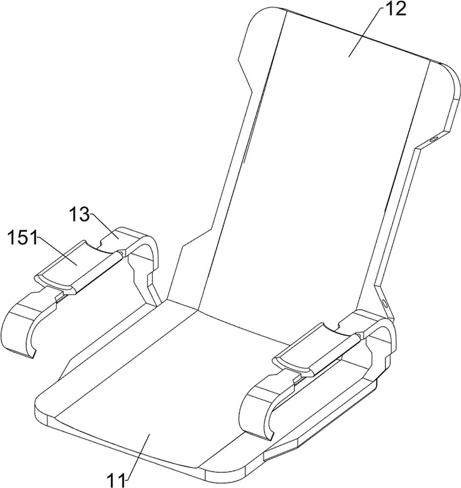
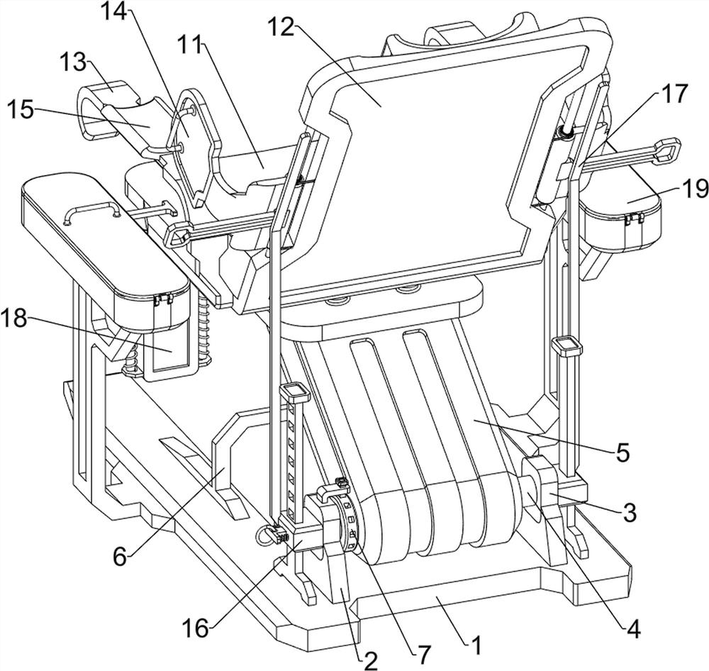
[0039] A chair for pediatric blood draws, such as Figure 1-8As shown, it includes a fixing plate 1, a first fixing block 2, a first sliding block 3, a first connecting shaft 4, a connecting frame 5, a first fixing frame 6, a chuck 7, a second fixing block 8, a first card Block 9, first spring 10, seat cushion 11, back cushion 12, armrest 13, control mechanism 14 and hand warmer mechanism 15, the upper side of the rear of the fixed plate 1 is symmetrically provided with a first fixed block 2, a first fixed block 2 A first sliding block 3 is connected to the upper clamping, a first connecting shaft 4 is rotatably arranged between the two first sliding blocks 3, a connecting frame 5 is sleeved on the first connecting shaft 4, and the upper side of the middle part of the fixing plate 1 is welded There is a first fixing frame 6, the first fixing frame 6 is in contact with the connecting frame 5, the right part of the first connecting shaft 4 is sleeved with a chuck 7, and the oute...
Embodiment 2
[0044] On the basis of Example 1, as figure 1 , Figure 8 and Figure 9 As shown, it also includes an adjustment mechanism 16. The adjustment mechanism 16 includes a clamping plate 161, a guide plate 162, a second slider 163, a second clamping block 164 and a second spring 165. The left and right sides of the rear top of the fixed plate 1 are respectively A guide plate 162 and a clamping plate 161 are welded, and a second slider 163 is bolted on one side of the two first sliders 3 away from each other. The left and right second sliders 163 slide through the guide plate 162 respectively. and the clamping plate 161, the clamping plate 161 is provided with at least eight square grooves, and the second sliding block 163 on the right side is slidably provided with a second clamping block 164 matched with the square groove, and the second clamping block 164 Two second springs 165 are connected to the right side of the right second sliding block 163 .
[0045] When the operator mo...
Embodiment 3
[0047] On the basis of Example 2, as figure 1 , Figure 8 and Figure 10 As shown, a power mechanism 17 is also included, and the power mechanism 17 includes an inclined rod 171, a first contact plate 172 and a coil spring 173, and two inclined rods 171 are welded on the opposite side of the upper part of the two second sliding blocks 163, A first contact plate 172 is bolted on one side of the two shields 142 that are separated from the middle. A coil spring 173 is connected with the back pad 12 .
[0048] The operator adjusts the inclination angle of the back pad 12, so that the back pad 12 rotates clockwise around the first connecting shaft 4, the back pad 12 drives the guard plate 142 to rotate clockwise through the second connecting shaft 141, and the second connecting shaft 141 drives the A contact plate 172 rotates clockwise, the second first contact plate 172 is in contact with the oblique rod 171 during the clockwise rotation, and the first contact plate 172 is forc...
PUM
 Abstract
Description
Claims
Application Information
 - R&D
- Intellectual Property
- Life Sciences
- Materials
- Tech Scout
- Unparalleled Data Quality
- Higher Quality Content
- 60% Fewer Hallucinations
Browse by: Latest US Patents, China's latest patents, Technical Efficacy Thesaurus, Application Domain, Technology Topic, Popular Technical Reports.
© 2025 PatSnap. All rights reserved.Legal|Privacy policy|Modern Slavery Act Transparency Statement|Sitemap|About US| Contact US: help@patsnap.com


