
Spinal implant with surface protrusions

A surface protrusion, surgical implant technology, applied in the direction of spinal implants, joint implants, joint implants, etc., can solve the problem of increasing the time required to complete healing, increasing patient discomfort, and trouble for surgeons, etc. question

Pending Publication Date: 2022-08-02
BEACON BIOMEDICAL LLC
View PDF0 Cites 0 Cited by
  • Summary
  • Abstract
  • Description
  • Claims
  • Application Information

AI Technical Summary

Problems solved by technology

The two-step insertion of this spacer is often considered cumbersome by surgeons and can cause unnecessary damage to bone and tissue, increasing patient discomfort and the time needed to complete healing

Method used


Image

  • Spinal implant with surface protrusions
  • Spinal implant with surface protrusions
  • Spinal implant with surface protrusions

Examples


Embodiment Construction

[0035] While the invention may take various forms of embodiment, currently preferred, non-limiting embodiments are shown in the drawings and hereinafter described, with the understanding that this disclosure is to be considered as an example of the invention and is not intended to In limiting the invention to the specific embodiments shown.

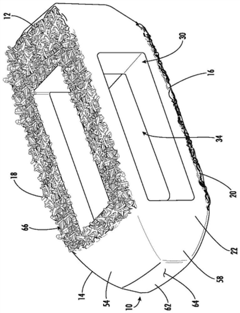
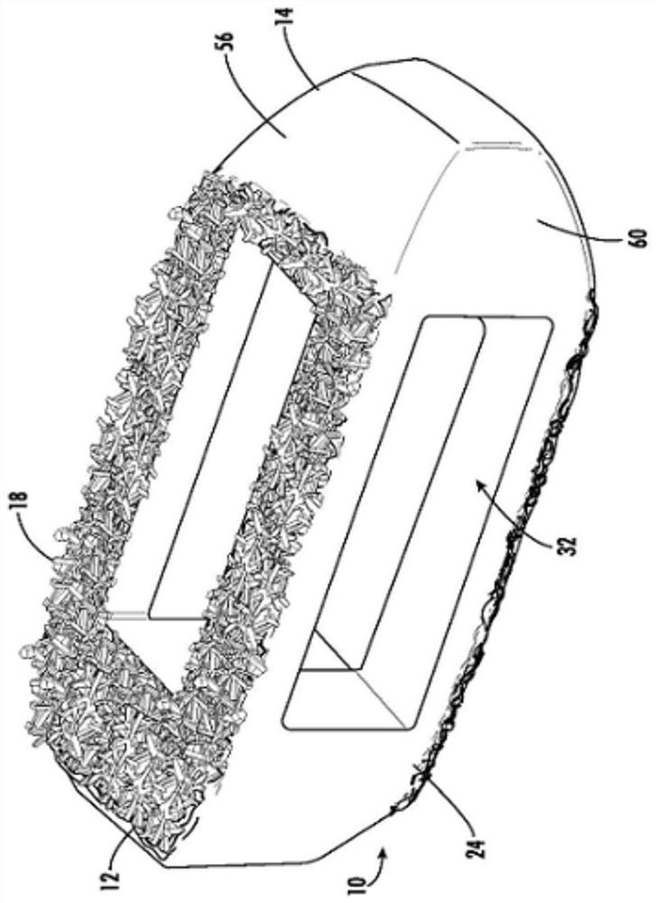
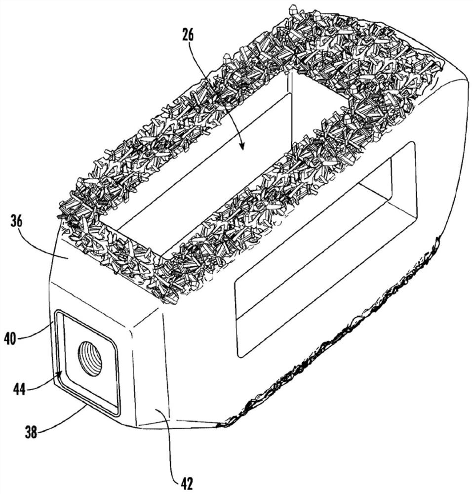
[0036] refer to Figure 1-10 , shows an illustrative embodiment of an interbody spacer having one or more surfaces having a unique surface pattern, generally referred to as an interbody spacer 10 . The interbody spacer 10 is preferably designed for use as an interbody spacer in spinal fusion procedures, wherein portions of the affected intervertebral disc are removed from between two adjacent vertebrae 102 and 104 (see Figure 16 ) and replaced with an interbody spacer 10 that provides segmental stability, corrects the deformity, and allows bone to grow between the two vertebrae to bridge the gap created by the discectomy. Preferably, t...


PUM

PropertyMeasurementUnit
sizeaaaaaaaaaa
sizeaaaaaaaaaa
diameteraaaaaaaaaa

Abstract

The invention relates to an intervertebral spacer for spinal surgery. The intervertebral spacer has one or more surfaces with a unique surface pattern. The interbody spacer is preferably designed for use in spinal fusion procedures in which the portion of the affected disc is removed from between two adjacent vertebrae and replaced with an interbody spacer that provides segment stability, which can correct deformity and allow bone to grow between the two vertebrae, and gaps caused by intervertebral disc resection are bridged. The intervertebral spacer has one or more unique surfaces intended to facilitate bone growth and attachment. The unique surface includes one or more surface protrusions, generally referred to as a pattern or matrix of surface protrusions, which may be arranged to form unique patterns and structures.

Description

[0001] Field of Invention [0002] The present invention relates to bone fixation devices and procedures for placing these devices in an individual. More particularly, the present invention relates to a device with surface protrusions for spinal fusion, and to a unique surface for surgical procedures. Background technique [0003] Medical procedures often require the use of surgical hardware. A common surgical hardware used by surgeons in spine-related surgery is a caged implant. Typical cage implants are porous, made of strong plastic or titanium, and inserted into various sections or anatomical features of the spine, including the cervical, thoracic, lumbar, sacroiliac joints, and articular surfaces. For example, degeneration of the intervertebral disc, particularly the nucleus pulposus, results in a reduction in the height of the affected disc space, which is associated with weakening of the annulus fibrosus and ligaments. As a result, the spine becomes unstable and more...

Claims


Application Information

Patent Timeline
Patent Type & Authority Applications(China)
IPC IPC(8): A61F2/44A61F2/46A61F2/30
CPCA61F2/4455A61F2/30771A61F2/447A61F2/4611A61F2/442A61F2002/30962A61F2002/30841A61F2002/3092A61F2002/30971A61F2002/30784A61F2002/30894A61F2002/3093A61F2310/00023A61F2002/30985A61F2002/30904A61F2002/30836A61F2002/4629A61F2002/4495A61F2002/30011A61F2002/30892A61F2002/30891A61F2002/30593A61F2002/30807
Inventor D·泰
Owner BEACON BIOMEDICAL LLC
Learn More