Embedded stranding machine with compact structure

A compact structure and stranding machine technology, which is applied in thin material processing, electrical components, cable/conductor manufacturing, etc., can solve the problems of large equipment footprint, waste of factory space, and complex structure, etc., to reduce the footprint, Improving utilization rate, streamlining and reasonable effect

Pending Publication Date: 2022-08-02
ZHONGSHAN GLAMOR OPTOELECTRONICS TECH
View PDF3 Cites 1 Cited by
  • Summary
  • Abstract
  • Description
  • Claims
  • Application Information

AI Technical Summary

Problems solved by technology

[0002] In the production process of LED light strings, it is necessary to twist the connected LED light strips and wires (two power lines, etc.). The equipment for this work is a twisting machine. A production method and device for high-speed stranded wires. The wire supply stator, the first stranded wire rotor, and the second stranded wire rotor are installed in a support frame, and form a row with equipment such as a traction mechanism, a wire arrangement mechanism, and a winding mechanism. Open, another example is that the patent literature with the publication number CN206379216U discloses a kind of equipment for fixing the lay length of twisted-pair cables. , that is to say, the current stranding machine is separated from the stranding mechanism and the take-up mechanism, and the two are arranged in a row. The production line is too long, and an additional traction mechanism is required, which also leads to complex structure and high cost of the equipment

Method used


Image

  • Embedded stranding machine with compact structure
  • Embedded stranding machine with compact structure
  • Embedded stranding machine with compact structure

Examples


Embodiment Construction

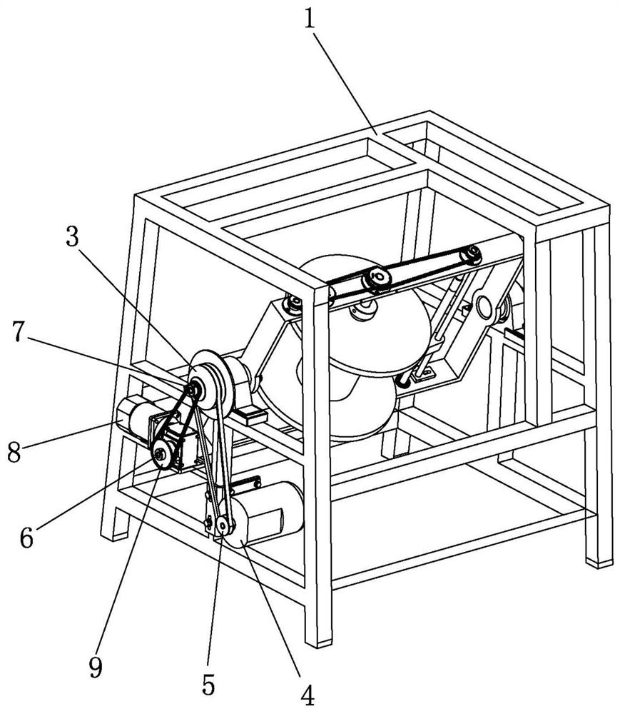
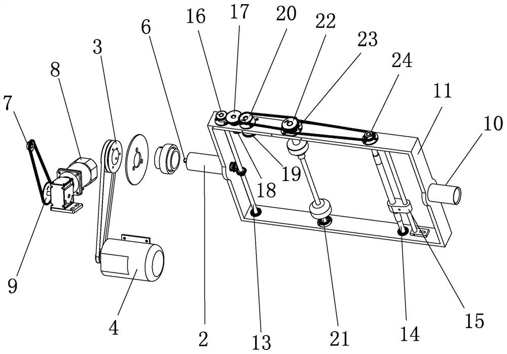
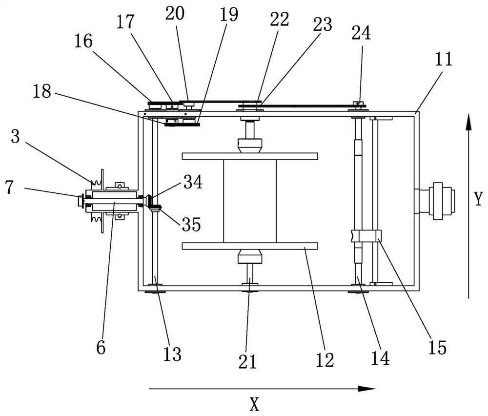
[0022] refer to Figure 1 to Figure 5 , an embedded stranding machine with a compact structure, which is characterized in that it includes a stranding wire take-up mechanism, and the stranding wire take-up mechanism includes a mounting frame 1, a stranding rotor 11 and a winding mechanism; The left and right sides are respectively installed on the mounting frame 1 through the X-direction first stranded wire shaft 2 and the second wire stranded wire shaft 10; 2 is a hollow shaft, and a speed regulating shaft 6 is coaxially installed in the first stranded wire shaft 2; the inner end of the first stranded wire shaft 2 is fixedly connected with the stranded wire rotor 11, and the outer end is connected with a power motor 4; The winding mechanism includes a Y-direction transmission shaft 13, a winding shaft 21 and a spool 14. The transmission shaft 13, the winding shaft 21 and the spool 14 are linked by a transmission mechanism. The transmission shaft 13, the winding shaft 21 The ...


PUM


Abstract

The invention discloses an embedded stranding machine with a compact structure, which comprises a stranded wire take-up mechanism, and the stranded wire take-up mechanism comprises a mounting rack, a stranded wire rotor and a winding mechanism. The left side and the right side of the wire twisting rotor are installed on the installation frame through a first wire twisting shaft and a second wire twisting shaft respectively, and a speed adjusting shaft is coaxially installed in the first wire twisting shaft. The winding mechanism comprises a transmission shaft, a winding shaft and a winding displacement shaft which are linked, a winding displacement sliding block is installed on the winding displacement shaft, the winding reel is installed in the wire twisting rotor through the winding shaft, the structure is compact, by means of the wire guiding mechanism and the guiding wheel, the placing position of the pay-off device does not need to be arranged in a line with the wire twisting and winding mechanism, the occupied area of production equipment is effectively reduced, and the production efficiency is improved. The power motor is utilized to link the stranding rotor, the winding reel and the winding displacement sliding block through a plurality of groups of transmission relations, so that the functions of stranding, winding and winding displacement are realized, and the structure is ingenious, simple and reasonable.

Description

technical field [0001] The invention relates to an automatic processing equipment, in particular to an LED lamp string stranding machine. Background technique [0002] In the production process of LED light strings, it is necessary to twist the connected LED light bars and wires (two power wires, etc.), and the equipment to complete this work is a twisting machine. A production method and device for high-speed stranded wire, the wire supply stator, the first stranded wire rotor and the second stranded wire rotor are installed in a support frame, and formed in a line with equipment such as a traction mechanism, a wire arrangement mechanism and a winding mechanism Another example is that the patent document whose publication number is CN206379216U discloses a kind of equipment for fixing twisted-pair cable lay length, and the equipment such as take-up roller group, traction mechanism, guide wheel group, and pay-off system are arranged in a row. , that is to say, the current s...

Claims


Application Information

Patent Timeline
Patent Type & Authority Applications(China)
IPC IPC(8): H01B13/02B65H57/14B65H54/553B65H54/44B65H54/70B65H63/00
CPCH01B13/0207H01B13/0264B65H57/14B65H54/553B65H54/44B65H54/70B65H63/006B65H2701/341
Inventor 孔令华丁孝君黄云毛勇斌柯贤安
Owner ZHONGSHAN GLAMOR OPTOELECTRONICS TECH
Why Eureka
Try Eureka