Oil well anti-blocking process for petroleum mechanical exploitation
A technology for petroleum machinery and oil wells, applied in the field of oil well anti-blocking technology
- Summary
- Abstract
- Description
- Claims
- Application Information
AI Technical Summary
Problems solved by technology
Method used
Image


Examples
Embodiment 1
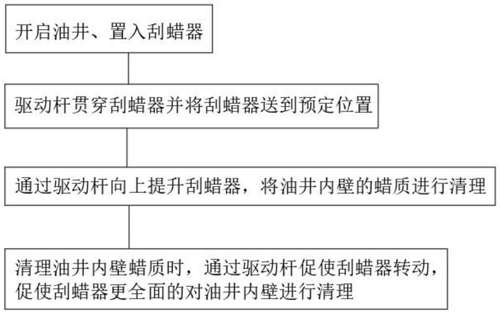
[0046] see figure 1 , an oil well anti-blocking process for petroleum mechanical exploitation, comprising the following steps:
[0047] S1. A wax scraper is built into the oil well;
[0048] S2. Insert the drive rod through the wax scraper, and push the wax scraper to go deeper into the oil well. A plurality of scrapers 29 are inclined on the wax scraper through the elastic connecting rod 28, and each scraper 29 is distributed in a circular array with the drive rod as the axis ;
[0049] S3. When the wax scraper reaches the predetermined position, lift the wax scraper upward through the drive rod, and the scraper 29 on the wax scraper cleans the wax on the inner wall of the oil well;
[0050] S4. While lifting the wax scraper upward through the driving rod, rotate the driving rod to make the wax scraper rotate, so as to completely clean the wax on the inner wall of the oil well.
Embodiment 2
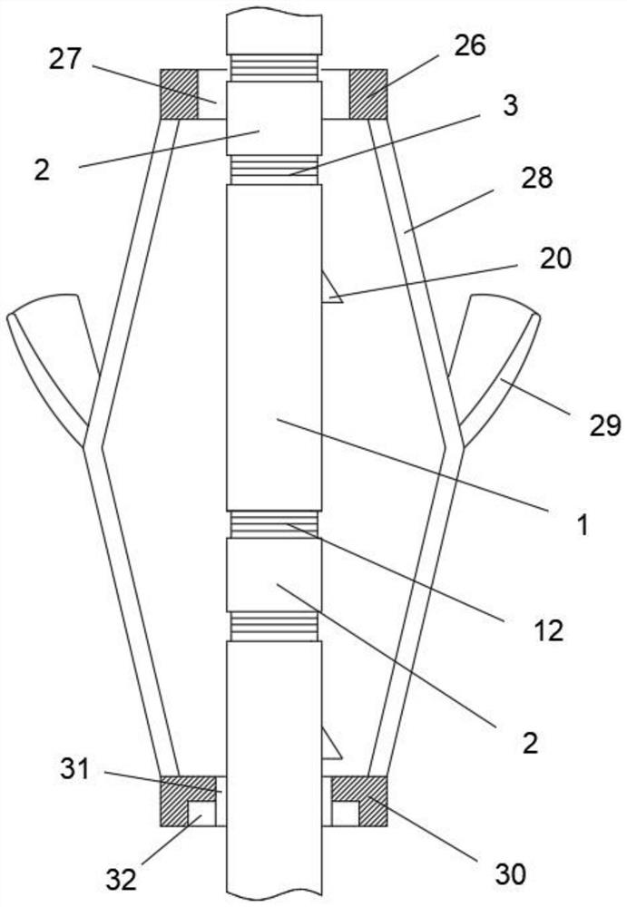
[0052] see Figure 2-7 , this embodiment further elaborates on the structure in Embodiment 1. The wax scraper includes a top collar 26 and a bottom collar 30. The top collar 26 and the bottom collar 30 are connected by an elastic link 28, and the elastic connection A scraper 29 is also installed on the rod 28, and the scraper 29 is inclined upward;
[0053] The driving rod passes through the upper ring hole 27 of the top collar 26 and the lower ring hole 31 of the bottom collar 30;
[0054] The drive rod is formed by interconnecting a plurality of modular rod structures. The modular rod structure is elastically installed with a first resistance block 20 for pushing the wax scraper downward, and a second resistance block for lifting the wax scraper upward. block 16, the first interference block 20 and the second interference block 16 are alternately hidden with the interior of the modular rod structure;
[0055] The first resisting block 20 is provided with a first resisting ...
Embodiment 3
[0061] see Figure 2-7 , this embodiment further elaborates on the structural aspects in Embodiment 2. The modular rod structure includes a module outer cylinder 1 and a module inner cylinder 19. Between two adjacent modular rod structures, the two module outer cylinders 1 Connected to each other, the inner cylinders 19 of the two modules are connected to each other;
[0062] In a modular rod structure, the inner module cylinder 19 is slidably installed in the outer module cylinder 1 , and the inner module cylinder 19 is elastically provided with a first interference block 20 and a second interference block 16 . The resisting inclined surface 22 is set obliquely downward, and the second resisting inclined surface 15 on the second resisting block 16 is set obliquely upward;
[0063] The inner cylinder 19 of the module is provided with an upper through hole 21 for accommodating the first resistance block 20, and a lower through hole 17 for accommodating the second resistance bl...
PUM
 Abstract
Description
Claims
Application Information
 - Generate Ideas
- Intellectual Property
- Life Sciences
- Materials
- Tech Scout
- Unparalleled Data Quality
- Higher Quality Content
- 60% Fewer Hallucinations
Browse by: Latest US Patents, China's latest patents, Technical Efficacy Thesaurus, Application Domain, Technology Topic, Popular Technical Reports.
© 2025 PatSnap. All rights reserved.Legal|Privacy policy|Modern Slavery Act Transparency Statement|Sitemap|About US| Contact US: help@patsnap.com