Safety lifting platform for exterior wall painting for building engineering construction
A technology for safe lifting and construction engineering, applied in construction, building structure, accessories of scaffolding, etc., can solve the problem of single function of the lifting platform for painting, and achieve the effect of improving convenience, high flexibility, and improving painting effect.
- Summary
- Abstract
- Description
- Claims
- Application Information
AI Technical Summary
Problems solved by technology
Method used
Image
Examples
Embodiment 2
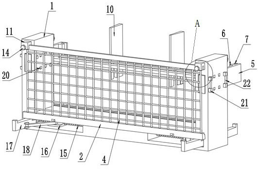
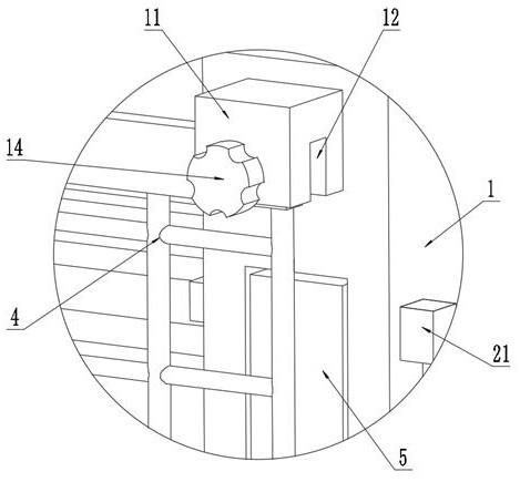
[0040] Example 2, which differs from Example 1 in that, as figure 2 , image 3 , Image 6 and Figure 8 As shown, the protective structure includes a rotating shaft 3 rotatably arranged on the pedal 2 and a protective net 4 wound on the rotating shaft 3 . The outer end of the pedal 2 exposes the carrier frame 1 , and a protective structure is provided on the end of the pedal 2 . The corresponding position of the pedal 2 is provided with a cavity with an opening at the upper end. The rotating shaft 3 is connected in the cavity of the pedal 2 through a coil spring. Exposed outside the opening for easy deployment. The carrier frame 1 is provided with a protective fixing structure for fixing the unfolded protective net 4 . Both sides of the carrying frame 1 of the present invention are provided with pedals 2 that can be pulled out. When using one side pedal 2, the other side pedal 2 is in the state of retracting the bottom of the carrier 1, and the protective net 4 on this ...
Embodiment 3
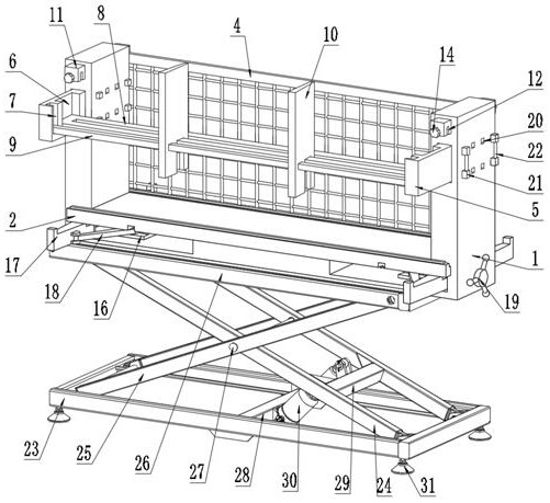
[0044] Example 3, the difference from Example 1 is that, as figure 1 As shown, the material load-bearing structure includes: two pull-out plates 5 and a load-bearing plate 8, the two pull-out plates 5 are respectively detachably arranged on the upper ends of the carrier frame 1, and the two pull-out plates 5 are opposite to each other. One side is provided with a vertical first groove 6, the bottom end of the first groove 6 is closed, and the two ends of the load-bearing plate 8 are respectively located in the two first grooves 6 to be supported and placed in the first groove. Bottom end of slot 6.
Embodiment 4
[0045] Example 4, the difference from Example 3 is that, as figure 2 As shown, the carrier frame 1 is provided with a fixing assembly for fixing the pull-out plate 5; the fixing assembly includes: a plurality of pins 21 and a plurality of grip rods 22; The through slot into which the plate 5 is inserted, the carrier 1 and the pull-out plate 5 are provided with a plurality of insertion holes 20, a plurality of the plug pins 21 are respectively inserted into the insertion holes 20, and a plurality of the handle bars Both ends of 22 are respectively connected between a plurality of the plugs 21 .
[0046] In the specific implementation process, it should be noted that when the pull-out plate 5 needs to be installed, the pull-out plate 5 is inserted into the through slot of the carrier frame 1, and then the staff holds the handle bar 22 and inserts the latch 21 into the In the slot, the fixing of the two pull-out plates 5 is completed, and the installation of the bearing plate 8...
PUM
 Abstract
Description
Claims
Application Information
 - R&D
- Intellectual Property
- Life Sciences
- Materials
- Tech Scout
- Unparalleled Data Quality
- Higher Quality Content
- 60% Fewer Hallucinations
Browse by: Latest US Patents, China's latest patents, Technical Efficacy Thesaurus, Application Domain, Technology Topic, Popular Technical Reports.
© 2025 PatSnap. All rights reserved.Legal|Privacy policy|Modern Slavery Act Transparency Statement|Sitemap|About US| Contact US: help@patsnap.com


