
External wall thermal insulation structure and external wall thermal insulation construction method

A technology for external wall insulation and thermal insulation boards, applied in the direction of thermal insulation, walls, building components, etc., can solve the problems of insufficient safety and low bonding strength, and achieve the effect of safe and reliable construction, reliable fixing and thermal insulation effect

Pending Publication Date: 2022-08-02
BEIJING BUILDING MATERIALS ACADEMY OF SCI RES
View PDF8 Cites 2 Cited by
  • Summary
  • Abstract
  • Description
  • Claims
  • Application Information

AI Technical Summary

Problems solved by technology

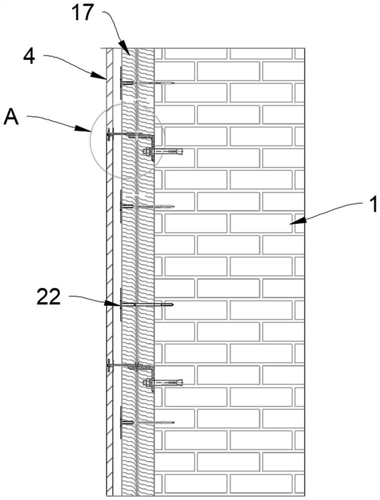
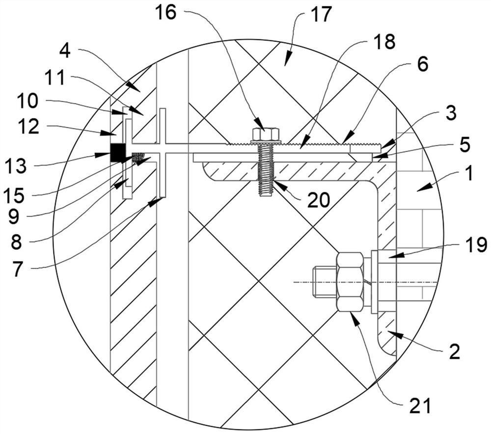
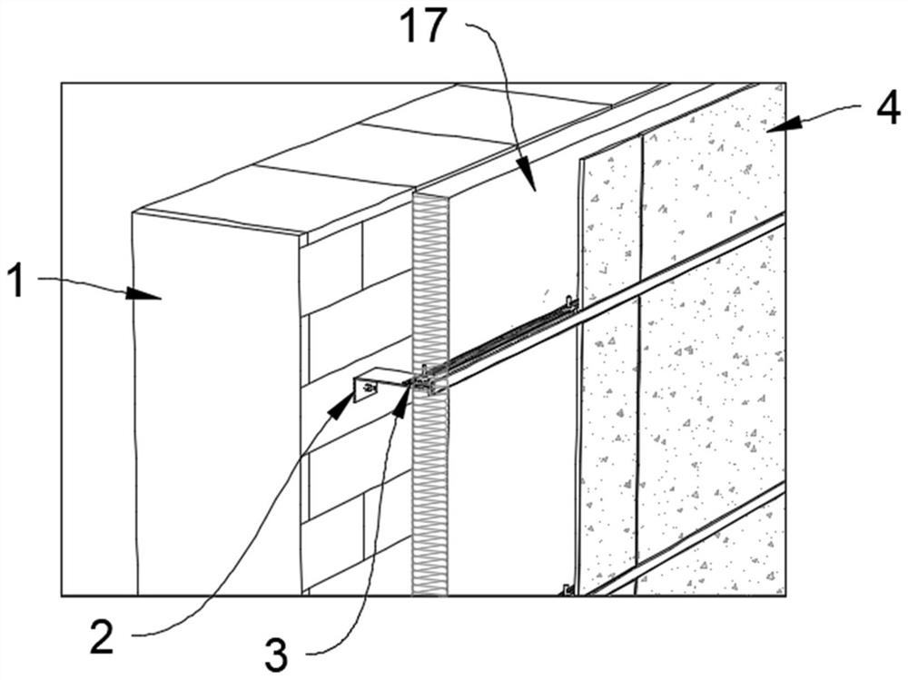
[0004] The invention provides an external wall thermal insulation structure, which is used to solve the technical problems of low bonding strength and insufficient safety during the thermal insulation renovation of the external walls of old residential quarters in the prior art, to realize the firm fixing of the thermal insulation board and the decorative board, and to lift the construction at the same time convenience and safety

Method used


Image

  • External wall thermal insulation structure and external wall thermal insulation construction method
  • External wall thermal insulation structure and external wall thermal insulation construction method
  • External wall thermal insulation structure and external wall thermal insulation construction method

Examples


Embodiment Construction

[0032] The embodiments of the present invention will be described in further detail below with reference to the accompanying drawings and examples. The following examples are intended to illustrate the present invention, but not to limit the scope of the present invention.

[0033] In the description of the embodiments of the present invention, it should be noted that the terms "center", "portrait", "horizontal", "top", "bottom", "front", "rear", "left", "right" , "vertical", "horizontal", "top", "bottom", "inside", "outside", etc. indicate the orientation or positional relationship based on the orientation or positional relationship shown in the accompanying drawings, only for the convenience of describing this Inventive embodiments and simplified descriptions are not intended to indicate or imply that the devices or elements referred to must have a particular orientation, be constructed and operate in a particular orientation, and therefore should not be construed as limitin...


PUM


Abstract

The invention relates to an outer wall heat preservation structure and an outer wall heat preservation construction method.The outer wall heat preservation structure comprises a connecting piece, a decorative plate clamping anchor piece, a decorative plate and a heat preservation plate, the connecting piece is suitable for being fixed to a base layer wall, the connecting piece is provided with two connecting faces, the two connecting faces are provided with an anchoring long hole and an internal thread through hole respectively, and the anchoring long hole is used for being connected with the base layer wall; the decorative plate clamping and anchoring part is provided with a connecting long hole, the connecting long hole and the internal thread through hole are suitable for being fastened through a hexagonal flange bolt, the decorative plate is fixed to the side, away from the connecting part, of the decorative plate clamping and anchoring part, and the heat preservation plate is arranged between the base layer wall body and the decorative plate and suitable for being connected with the base layer wall body through the heat preservation plate anchoring part. A gap is reserved between the side, away from the base layer wall body, of the insulation board and the decorative board. A gap is formed between the heat preservation plate and the decorative plate, and water can flow downwards along the decorative plate and cannot enter the heat preservation plate to affect the heat preservation performance when the problems of cracking, water leakage and the like occur at a plate seam of the decorative plate.

Description

technical field [0001] The invention relates to the technical field of external wall thermal insulation, in particular to an external wall thermal insulation structure and an external wall thermal insulation construction method. Background technique [0002] At present, in the thermal insulation renovation of the external walls of old residential areas, most of them copy the external thermal insulation method of thin plastered external walls combined with bonding and anchoring of new buildings, which has certain requirements on the "health degree" of the base wall. Most of the old communities are brick-concrete structures with sintered solid brick masonry. A large number of old buildings have been used for more than 20 years, and even some have been used for more than 30 years. Because the walls have been exposed to wind and sun for a long time, rain, freezing and thawing, etc. , the wall will appear hollow, cracking, peeling, base layer powder, salting damage and other prob...

Claims


Application Information

Patent Timeline
Patent Type & Authority Applications(China)
IPC IPC(8): E04B1/76E04B1/80E04B2/00E04F13/22E04F13/072E04F13/076E04G21/00
CPCE04B1/76E04B1/80E04B2/00E04F13/0801E04F13/08E04F13/0891E04F13/0894E04G21/00Y02B30/90
Inventor 王正华路国忠李雨洋
Owner BEIJING BUILDING MATERIALS ACADEMY OF SCI RES
Learn More