Jig clamp mechanism with accurate positioning function
A jig fixture, precise positioning technology, applied in positioning devices, clamping, manufacturing tools, etc., can solve the problems of reduced yield, workpiece control accuracy, single function, etc., to improve processing efficiency and processing accuracy, limit position And the effect of good positioning effect and high clamping stability
- Summary
- Abstract
- Description
- Claims
- Application Information
AI Technical Summary
Problems solved by technology
Method used
Image
Examples
Embodiment 1
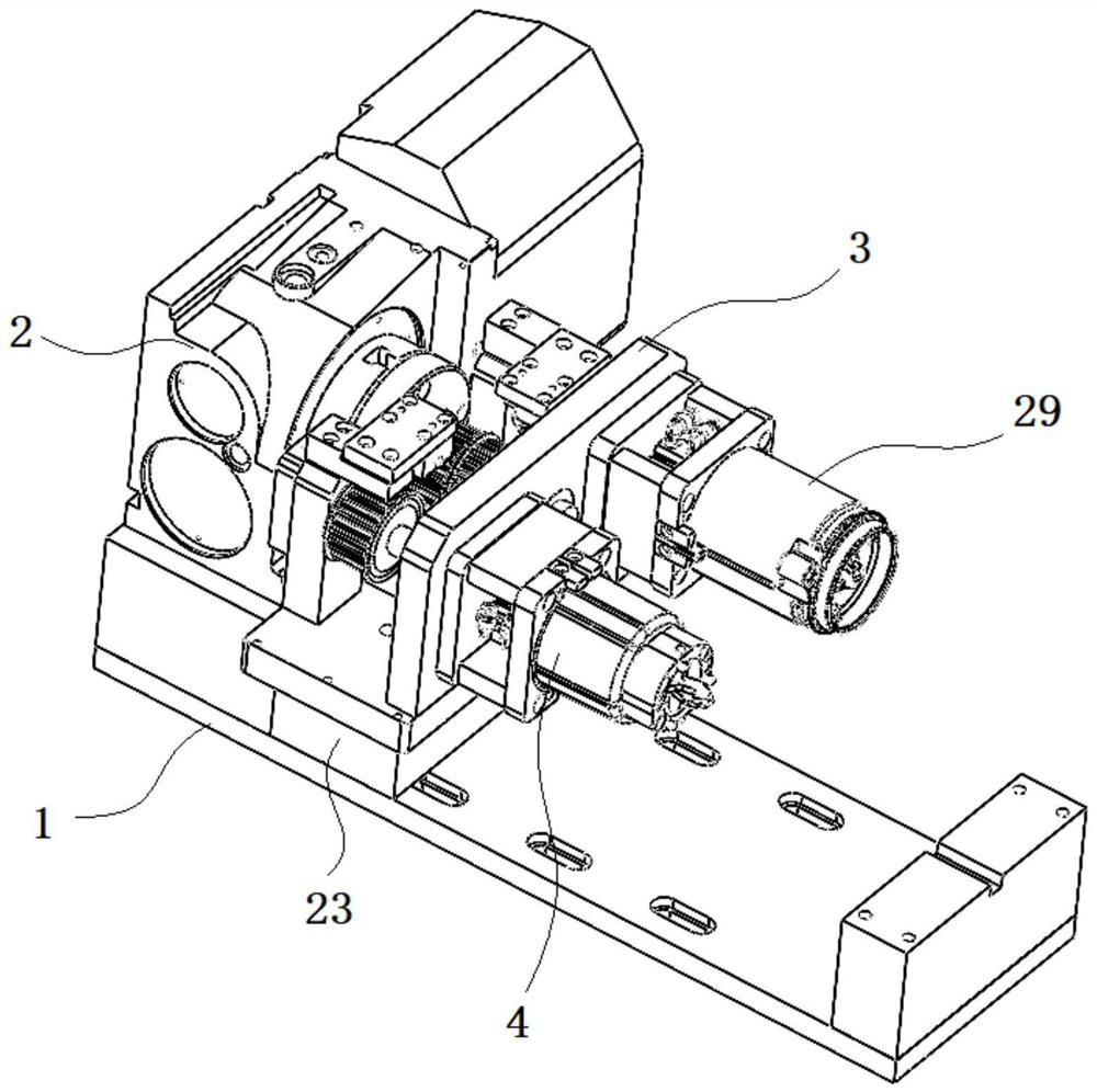
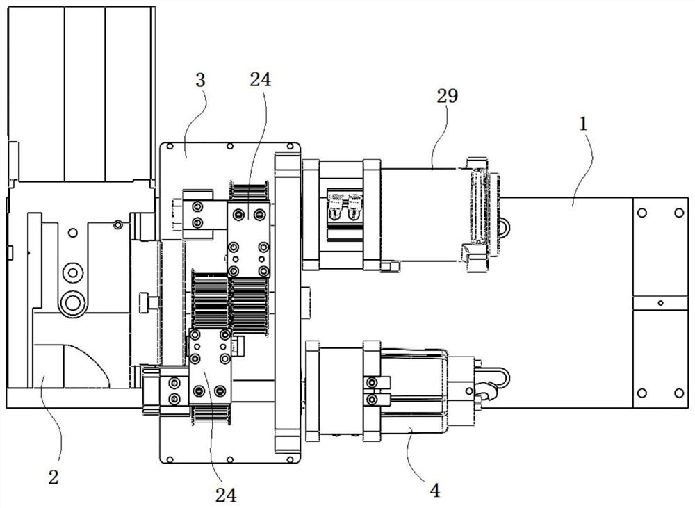
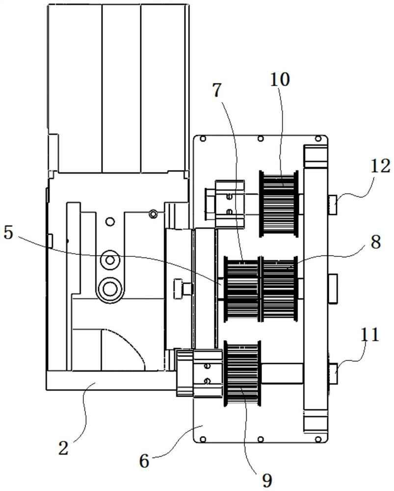
[0026] An accurate positioning jig clamp mechanism in this embodiment includes an installation base 1, and is characterized in that a drive device 2, a transmission mechanism 3 and a gripper mechanism 4 are provided on the installation base 1. The drive device 2 is fixedly arranged on one side of the installation base 1, including the transmission shaft 5, the transmission mechanism 3 includes the installation seat 6, the first main synchronous pulley 7, the second main synchronous pulley 8, and the first slave synchronous pulley 9 , the second slave synchronous pulley 10, the first output shaft 11 and the second output shaft 12, the clamping jaw mechanism 4 is divided into two groups, which correspond to the first output shaft 11 and the second output shaft 12 one-to-one respectively, and the clamping jaw mechanism 4 is divided into two groups. The claw mechanism 4 includes a clamp base 13, a cylinder 14, a positioning seat 15 and a clamping claw 16;
[0027] The drive device...
Embodiment 2
[0029] A precise positioning jig clamp mechanism in this embodiment, wherein the transmission shaft 5 extends into the mounting seat 6 and is movably connected with the mounting seat 6 through a bearing, the first main synchronous pulley 7, the second The main synchronous pulleys 8 are fixedly connected to the transmission shaft 5, are arranged coaxially, and are controlled to rotate by the driving device 2. The first output shaft 11 and the second output shaft 12 are respectively arranged on the horizontal sides of the mounting seat 6, It is movably connected to the mounting seat 6 through a bearing. The first slave synchronous pulley 9 and the second slave synchronous pulley 10 are respectively fixed on the first output shaft 11 and the second output shaft 12, and the first main synchronous pulley 7 It is connected with the first slave synchronous pulley 9 through a synchronous tape for transmission, and the second main synchronous pulley 8 and the second slave synchronous pu...
Embodiment 3
[0032] In the present embodiment of a precise positioning jig clamp mechanism, the clamp bases 13 on the two sets of the clamping jaw mechanisms 4 are respectively fixed and installed on one end of the first output shaft 11 and the second output shaft 12, and the The air cylinder 14 is fixedly arranged in the clamp base 13, the air cylinder 14 includes a telescopic shaft 17, a positioning block 25 is fixedly connected to the clamp base 13, and is fixedly connected to the positioning seat 15 through the positioning block 25, and the clamping jaw 16 is formed by Two pressing claws 18 are formed. The two pressing claws 18 are arranged in a cross, and are hingedly connected in the middle, and are hingedly mounted on the positioning seat 15. The two ends of the pressing claws 18 are the working part 19 and the driving part 20 respectively. The driving part 20 is connected with a connecting rod 21; the working part 19 is hook-shaped;
[0033] In this embodiment, the clamping jaw mec...
PUM
 Abstract
Description
Claims
Application Information
 - Generate Ideas
- Intellectual Property
- Life Sciences
- Materials
- Tech Scout
- Unparalleled Data Quality
- Higher Quality Content
- 60% Fewer Hallucinations
Browse by: Latest US Patents, China's latest patents, Technical Efficacy Thesaurus, Application Domain, Technology Topic, Popular Technical Reports.
© 2025 PatSnap. All rights reserved.Legal|Privacy policy|Modern Slavery Act Transparency Statement|Sitemap|About US| Contact US: help@patsnap.com


